To fabricate printed circuit boards, and design PCB schematics and PCB layouts, one will need to utilize several types of software. Regardless of the level of the circuit design, there is a wide range of tools, procedures, and disciplines one must use. These tools must meet the demands of the manufacturer or design and enable them to create their board – quickly.
When it comes to bARE PCB construction, it is all about taking one step back and two steps forward. Plus, the task at hand ultimately determines the best tool to use. Schematic capture and board layout are essential to each other, and this is where the circuit maker features. This article is all about the Altium Circuit Maker, how it impacts PCB development, and how to use it for PCB design.
What Is a Circuit Maker (Altium)?
Altium circuit maker is electronic design automation (EDA) software specifically created for PCB designs for the CircuitMaker community. It comes in freeware, with hardware that makes the software ideal for commercial as well as non-commercial purposes. Altium circuit maker is one of the two types of circuit makers, the other being Protel; both are popular among PCB manufacturers.
Altium circuit maker utilizes the same Altium Designer to integrate printed circuit board design and schematic capture. It is a powerful, easy-to-use simulation tool and schematic capture that lets you design electronic circuits and netlists. Plus, the software offers fast but accurate analog, digital, and hybrid (combination of analog and digital) simulations.
Is Altium Circuit Maker Free?
Altium Circuit Maker is a free, desktop-based software tool that supports PCB designing on Windows; all you need is the internet to connect. The circuit maker requires a free account to represent the circuitmaker community and an active internet connection to use the software. Furthermore, it gives users the chance to have five private projects, with the sandbox mode for practicing. Even though it is free, there is no limit to the projects users can have, nor is there a hard limit on board complexity.
Altium is completely free to use, giving users access to a world of rich features. This includes the opportunity to work with other members of the circuitmaker community on a project.
How Do You Use the Altium Circuit Maker?

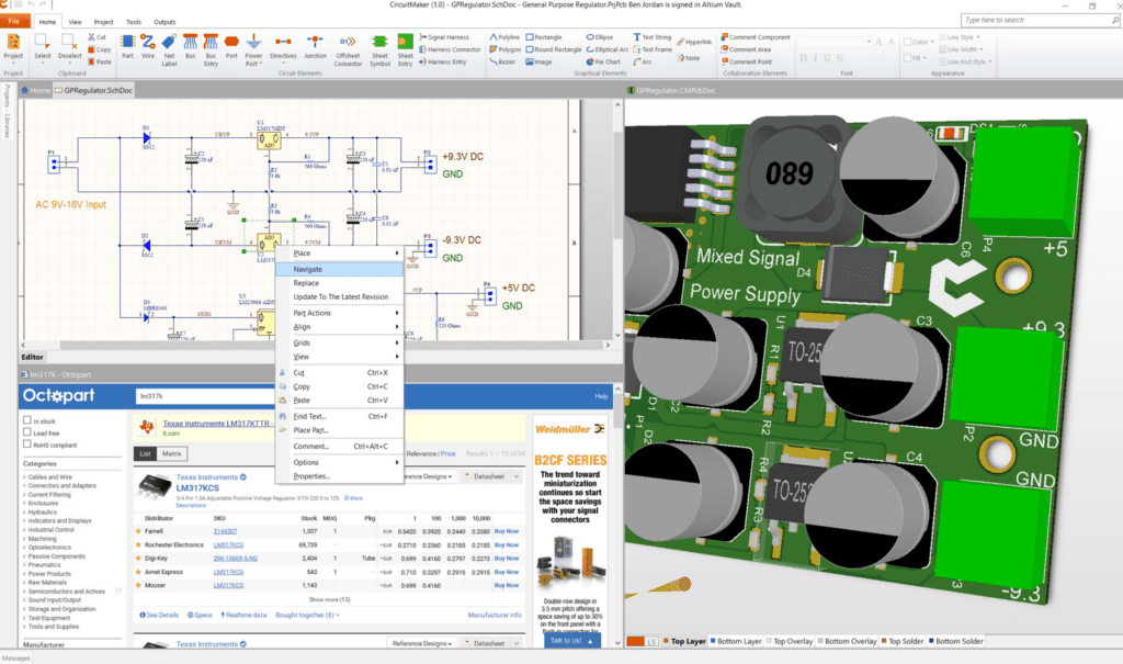
Using the Altium Circuit Maker starts with populating schematic capture and their associated data using symbols. This may mean making new symbols for pinouts and parts that do not follow the standard designs. To start with, click on the toolbar button with a transistor symbol; always click this button when you want to run the software.
Next, choose “Grid” for neat diagrams and click on “Snap to grid;” if grids are distracting for you, you may bypass this stage. Link outputs and inputs together with the wire tool; click on a connection point to add a wire.
Next, go to the Devices menu to choose gates; you can find simple devices and gates without browsing through the lists. To get a data logic switch, type “hotkey;” it is a common input device that alternates between 0 and 1. If you want to set several inputs at once, type a hex digit into the Hex pad to get four outputs.
What Are the Features of Altium Circuit Maker?
Altium is designed based on Altium Designer technology, offering a powerful engine and streamlined interface. Its features include:
- A great community library with several components, including the free PCB design tool and supported by the Octopart database for easy placement of components in designs;
- An aesthetically-pleasing, easy-to-use multi-sheet schematic editor for complex multi-sheet designs and SmartPDF output generation that works with the complex multi-sheet designs;
- Sixteen plane and sixteen signal layers and zero restrictions in working with the PCB dimensions;
- A Situs topological auto-router that works with design rules for quick creation of circuit boards using BGA and SMT fanout;
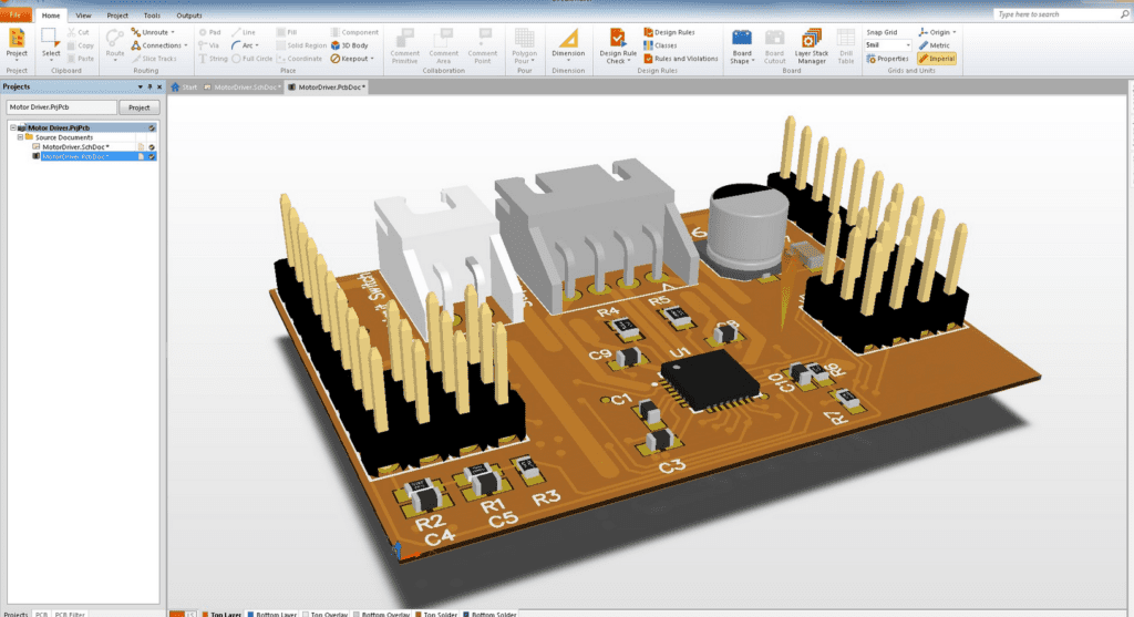
- Native 3D technology with industry standard cam outputs for viewing PCB layout in 3D as well as component clearance violations and overlap distances for the PCB layout or PCB dimensions;
- Enables project sharing with either the whole circuitmaker community or certain authors who have specialized in interactive routing modes;
- An interactive push and shove routing that push obstacle avoidance for the PCB design software;
- DRC/DFM validated outputs for when you want to turn your design into a real board for NC drill. You can choose from either ODB++ or Gerber and NC Drill – or both; and
- One-click manufacturing to release your project to the community after designing the mechanical components, the interactive routing modes, and other parts.
Is Altium a CAD Designer?
Altium Designer is a CAD software tool that gives designers complete control over all aspects of their PCB design. There is no other design platform that offers all the essential MCAD and ECAD design tools in one place. With the Altium Designer, you can get an unprecedented amount of integration into the world of software development.
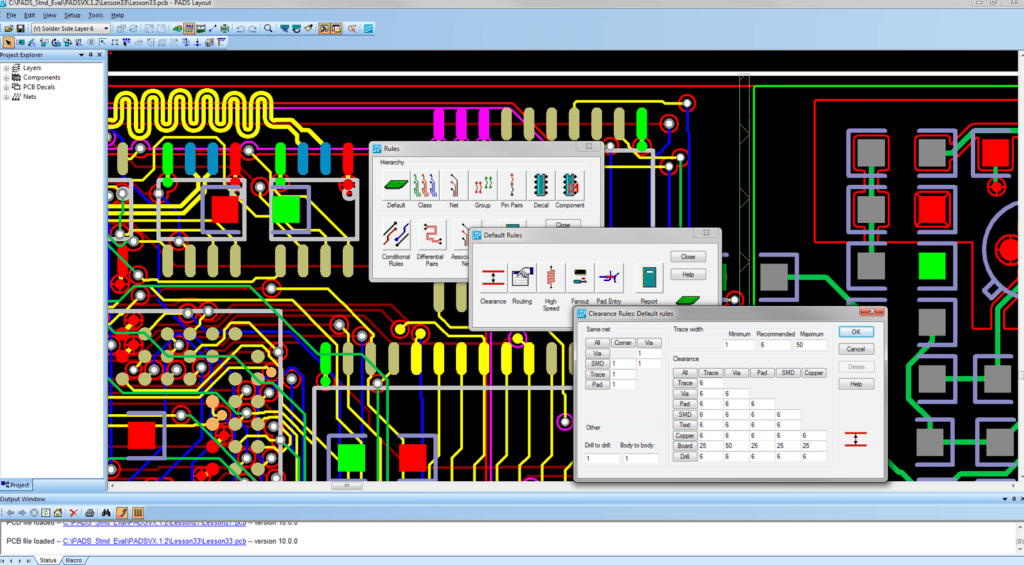
The integrated CAD design in Altium offers PCB designers interface with powerful PCB design tools for expediting the processes of layout and production planning following the right design rules while paying attention to interactively route multi-nets. Not following the laid down design rules PCB designers are to follow for Altium 365 will result in component clearance violations.
How to Create a New Schematic Using Altium Circuit Maker
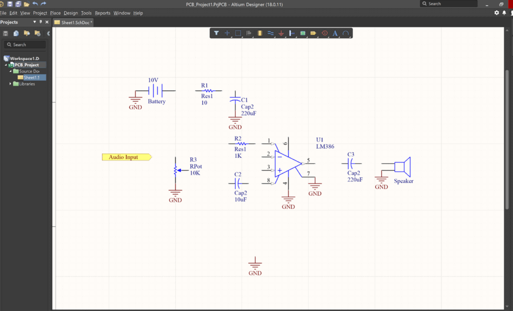
To create a new schematic on Altium Circuit Maker, go to the menu and click on File. From the popup menu, choose “New Project,” and enter the project name you wish to use; then, select Sandbox or Public. Next, click on Open Design, then Project->New Schematic; from the dropdown menu in Libraries, choose the component and then click on Octopart.
After this, you will be required to put the component type and package you wish to use for your new schematic. After that, click on “wire” to connect all the components; then, rename it and enter the value. When you are done, you need to check for errors; click on “Project->Compile” to do this.
How Do You Create PCB Footprints Using Altium Circuit Maker?
First, click on the required Project after which you select Add New PCB; this will lead you to the Footprint. When you are there, click on “Project” and select “Import Changes” from filename.Prjpcb. After this, completely select the needed components; drag them into the appropriate place. Ensure you keep the components close to each other, but also ensure they do not overlap.
After this, go to the Home Tab, under it click on “Route” to track the component. You can also track components by going under the Tool Tab and clicking on “Autoroute.”
Filling Copper in PCB Design with Altium Circuit Maker
You need to first adjust the board size to what you need before you start filling copper. To do this, go to the Board Section under the Home Tab and click on “Board Shape.” When you have adjusted the shape, you can now copper fill. To do this, go to the Pour Section in the Home Tab and click on “Polygon Pour.”
From the popup menu that shows up after clicking on Polygon Pour, choose the first option. Start clicking on each edge to fill copper; when you are done, press “ESC.” Click on the bottom layer tab to do the same thing for the bottom layer; then, click on the View Tab.
From the View Tab, click on “Switch to 3D” to view the newly designed printed circuit board in 3D. Lastly, save your design; under the Output Tab, click on “Gerber” to generate Gerber Files.
How Does the Altium Circuit Maker Work?
The Altium Circuit Maker utilizes the Altium Designer Technology to integrate PCB design and schematic capture. It features a schematic PCB editor that comes with circuit design and basic component placement. Additionally, the circuit maker includes multi-channel design and hierarchical design blocks; anyone with Altium can view uploaded schematics on the server. Furthermore, Altium Circuit Maker supports any incorporation with Octopart; it also supports drag-and-drop component placement.
Furthermore, Altium users can design missing schematic symbols dedicated to the server, which is also known as the Community Vault. Schematics transfer to a printed circuit board is streamlined in circuit makers because PCB footprints can attach to any component.
Can You Directly Export Production Files in Altium?
Altium allows you to directly export production files; it also lets you export the whole PCB as a 3D STEP model. However, this software is only available to Windows, and to use it, you must have a Windows license. Moreover, the Altium Circuit Maker does not support the export of design resources, but it lets you include personal mechanical components.
What Is Cross-Probing in Altium Circuit Maker?
The cross-probing functionality in the Altium Circuit Maker allows you to visualize data and real-time calculations. Some good examples include phasors for attenuation and gain and the different components of Bode plots. When you analyze the circuit at this level and pace, you will experience and enjoy a streamlined review process. Moreover, this function gives you an insight into downstream operators and the best and perfect way to modulate their work.
Why Should You Run Simulation Before Production?
Running simulation before production offers feedback; engineers can simulate worst-case signals to represent a bigger sample. Material details, basic circuit connections, and other pieces of information that determine early circuit simulations are provided by the manufacturer. However, the computational power one needs to analyze will not enable across-board simulation of all the feasible signals.
Nevertheless, a designer/engineer can always test the thermal properties of a printed circuit board when they integrate a similar degree of simulation. As such, you will spend less time during testing than you would if you had not run a simulation.
What Are the Benefits of Using Altium Circuit Maker?
With Altium CircuitMaker, you have the freedom to design with up to 16 plane and 16 signal layers with zero PCB dimension restrictions. Moreover, you can earn big with your designs thanks to the non-commercial clause in the software’s terms of use. Furthermore, Circuit Maker gives you up to five private projects and the freedom to choose who to share with – authors or customers. Meanwhile, the software has hundreds of thousands of components that you can place as easily as you search by design parameters.
With Circuit Maker, you can share your project with anyone, thus harnessing your skills and knowledge of teams for faster project completion. Also, since designs and all the components released to the broad design community can be modified by any member, you can build new designs with different features without starting from scratch.
Also, when you use Altium 365, you can access advanced features, follow up on the succinct release process of custom parts and other component models of professional manufacturing. That way, you can address signal delays of the created circuitmaker, review the IPC test point reports for placing components on the same engine or any of its own custom parts. By boycotting manual routing, you can auto complete the process and save time in the process.
How Can Hillman Curtis Help?
Although you can design a PCB with yourself by following the tutorial religiously, we still recommend getting professional PCB services for understanding how the custom schematic symbol works. Considering the dexterity, level of concentration, and amount of work that goes into PCB manufacturing, assembly, and the knowledge to route differential pairs. You have a better chance with world-leading PCB manufacturing and assembly companies such as Hillman Curtis. Hillman Curtis is a brand under RayMing Technology; it specializes in providing small and large companies worldwide with high-quality PCB services.
Hillman Curtis services include PCB fabrication, components sourcing and routing of output files, and PCB assembly, with more than ten years of experience in the industry. The company aims to give its customers high-quality products, from double-sided surface mount designs to complex multi-layer boards. You can take advantage of its genuine commitment to outstanding customer service and unparalleled technical expertise for your PCB needs.
Conclusion
If you are looking for better and more efficient PCB design tools, you can find them in Altium CircuitMaker or the Altium server. Altium 365 is a free software tool designed to help a PCB editor, manufacturers, hobbyists, and the circuitmaker community to turn their community library ideas into reality. It is a great schematic and PCB design software with a powerful engine and streamlined interface for easy PCB design. With Altium CircuitMaker, you can gather the skills and knowledge needed to transform your ideas into real-life products.
