FR4 is a common material used in PCB fabrication. This material is flame retardant and has got unique properties. High speed and high performance boards require good signal integrity. The need for heat dissipation in electronic devices is a must.
Most PCB boards that may not be subjected to harsh conditions may incorporate FR4. During the design of a board, a manufacturer should consider the application requirement of the board. FR4 thermal conductivity is well documented. Hence, in this article, we will shed more light on it.
What is FR4?
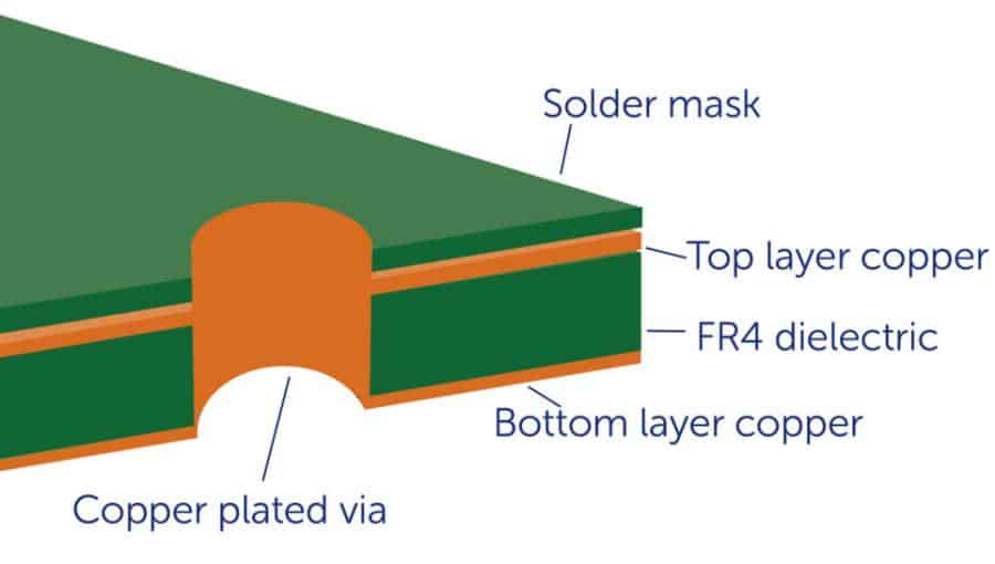
FR4 is a flame retardant material that comprises glass fiber epoxy laminate. It is a common material used for the fabrication of printed circuit boards. The FR means flame retardant. The “4” in FR4 means reinforced woven glass epoxy resin. This material complies with the UL94V-0 standard. FR4 is the major insulating backbone of most PCBs. This dielectric material is available in multilayer, double-sided, and single-sided boards.
FR4 material features great mechanical and electrical properties. This material is mechanically and thermally stable. It functions as an insulator in a circuit by isolating adjacent copper planes. FR4 thermal resistance is one of its major benefits. Thermal management is important in most electronic devices. Most of these devices work under varying temperatures.
Most PCB manufacturers use FR4 as the base of their circuit board. It is a highly-preferred material because of its great physical properties. FR4 conductivity describes how heat transfers through it. FR4 is a versatile material used for several applications. It is a strong material that prevents the spread of fire.
This material is the insulating backbone of a circuit board. It forms the base upon which the circuit is built. Manufacturers use adhesive or heat to laminate FR4 with one or more layers of copper.
Request FR4 Thermal Conductivity PCB Quote, Pls Send PCB Files to Sales@raypcb.com Now
Properties of FR4
FR4 is a great material that improves thermal management in PCBs. This material has got some unique properties.
Flame retardant
This is the most noticeable property of FR4. Flame retardant is the ability of a material to delay or prevent fire. Flame retardant materials are adaptable and versatile. This material produces great results when used for PCB manufacturing.
Low moisture absorption
FR4 features low moisture absorption. This means that this material won’t absorb water when immersed in water. FR4 has 0.10% of moisture absorption. This is very low.
Good electrical properties
To ensure impedance control, the electrical characteristics of a PCB material is important. Material with great electrical properties ensures they keep electrical charge in a given volume.
Thermal conductivity
FR4 thermal conductivity describes the way heat moves from hot to cold areas in a circuit. FR4 material is a good conductor of heat. It allows the transfer of heat around the circuit board.
Radiation resistant
FR4 is a great material for PCBs used for telecommunication. This material has the ability to resist radiation and thermal shock. FR4 PCB is ideal for applications that are frequently exposed to a high rate of radiation.
Glass transition temperature (Tg)
The Tg of a thermosetting polymer is associated with its CTE. The CTE increases when the temperature of the material is beyond Tg. Therefore, a PCB should operate in an environment where the temperature is lower than TG. When the temperature is more than Tg, the material will become more pliable.
What Factors Affect PCB Thermal Conductivity?
PCB thermal conductivity describes the ability of a PCB to transfer and conduct heat. It refers to how PCBs can transfer heat around its component. W/m/K represents the value of thermal conductivity. Thermal conductivity is a core aspect of PCB design. It helps engineers to determine how a circuit board could conduct heat.
PCB thermal conductivity is a parameter that needs special attention among manufacturers. However, there are factors that influence PCB thermal conductivity.
Thermal vias
To achieve effective PCB thermal conductivity, thermal vias play an important role. Thermal vias help to discharge heat off a component. These vias are holes placed on a circuit board. They provide more rooms for the heat to escape. Therefore, more thermal vias in a circuit board enhance thermal conductivity.
Trace geometries
If there are copper traces in a circuit board, you can achieve thermal conductivity. If these traces run along one end to another end, there will be high thermal conductivity. However, if the traces discontinue, the thermal conductivity decreases.
Internal layers
Internal layers can influence heat dissipation. More inner layers of copper can decrease the thermal conductivity of a circuit.
A PCB features electronic components, insulators, and conductive materials. Each of the materials on a circuit board features different thermal conductance.
Thermal Resistance in PCB
Heat management plays a crucial role in keeping components cool during operation. Arguably, FR4 is the commonest substrate material. However, it features a low thermal conductivity. This causes heat to remain close to hot components. Overheating in electronic devices can cause damage. Therefore, the need for a thermal management strategy. This will help dissipate heat from important components.
Thermal resistance in printed circuit boards is very important. Heat sinks and FR4 are a crucial part of thermal management. However, it is important to design your board to ensure thermal resistance. PCB manufacturers must use the right materials to achieve this.
It is crucial to understand what thermal resistance is. FR4 thermal resistance depends on its thermal conductivity. FR4 conductivity enables the transfer of heat from a warmer area to a cooler area at a quicker rate. Hence, the PCB will have a lower thermal resistance.
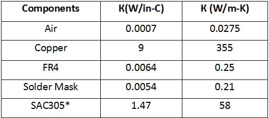
The various components and parts on a circuit board contribute to thermal conductivity. These components all feature different thermal conductivity. Hence, they conduct heat at different levels. To determine a PCB thermal resistance, consider the thermal resistance in each component. Therefore, FR4 thermal resistance and low thermal resistance copper determine PCB thermal conductivity.
The arrangements of copper elements in a PCB determine the PCB thermal resistance. You can measure the thermal conductivity of a PCB to determine thermal resistance.
Request FR4 Thermal Conductivity PCB Quote, Pls Send PCB Files to Sales@raypcb.com Now
How to Develop Thermal Management Strategy
The right placement of thermal vias can enhance heat transfer. If a PCB features more active components, you can place these components away from the board’s edge. This will help to prevent hot spots in the circuit board.
You can also use materials featuring high thermal conductivity to reduce thermal resistance in your board. A thermal simulation tool is also very helpful. It can determine an ideal thermal strategy for your circuit board. The copper in plane layers features high thermal conductivity. Hence, it offers a low resistance path for the transfer of heat from hot components.
Ensure you use inner ground/power plane layers when designing a high-frequency PCB. Also, you can dissipate heat away from the surface by putting copper pads below hot electronic components. These pads often have vias that link to an inner ground plane. Hence, this offers image protection for these components.
Another way to minimize thermal resistance in PCBs is by using heavier copper. Use heavier copper if a circuit board will operate at a higher current. FR4 material features low thermal conductivity. Therefore, this material features high thermal resistance. Metal core boards are a better option for thermal management. These boards allow heat transfer from a component at a faster rate.
FR4 thermal conductivity is 1.0 W/(m-K). Ceramic materials feature thermal conductivities within the range of 20 to 300 W/(m-K). When designing your layer stackup, consider thermal management in your PCB.
Limitations of FR4 Material in PCB
Unarguably, FR4 is a common material used in PCB manufacturing. The low cost and electrical insulation of this material make it a perfect choice. However, FR4 thermal conductivity is high. This single fact makes it not ideal for high-speed applications. The limitations of FR4 are below;
Controlled impedance
FR4 features no uniform Dk value like other high-speed board materials. As the frequency of FR4 increases, the dielectric constant changes. Dk tolerances for FR4 are about 10%. Dielectric constant variations in FR4 pose a great threat while regulating impedance values. Therefore, FR4 isn’t an ideal choice for boards with controlled impedance.
Temperature stability
FR4 isn’t an ideal choice for electronic devices that work under high temperatures. Furthermore, FR4 doesn’t support soldering free of lead. This is because the lead-free PCB assembly’s reflow temperature can be about 250 °C. This value is more than the glass transition temperature of most FR4 versions.
Insulating stability
When FR4 is exposed to high power or heat, it can deteriorate. Although this material is a good insulator, it has got its limits. If subjected to high heat, it will start conducting electricity.
Signal losses
This is a crucial aspect in circuit board design, especially in high-end applications. FR4 material features a high dissipation factor (Df). The Df is greater than that of high frequency materials. FR4 features a DF of about 0,020 while other high-frequency materials feature a Df of about 0.004. Lower Df results in lower signal loss. Another limitation is that the FR4 dissipation factor increases as signal frequency increases. Therefore, these circuit boards suffer higher signal losses.
Factors to Consider When Choosing FR4
FR4 is a stable material with reliable insulation. The dielectric characteristic of this material is usable. There is no doubt that FR4 plays a crucial role in PCBs. It is now common to use mineral fillers to replace a portion of the resin volume. The standard Tg value for FR4 is 130 °. You must consider some important factors when choosing FR4 material.
Thickness
You need to specify the thickness of the FR4 material you are using. FR4 thicknesses vary based on the project’s requirements. Although the thickness of a board may not be a crucial factor, it is an essential feature. The thickness of your FR4 material influences the functionality of your board. If space is important, a thinner FR4 is a better option.
Cost
This is an important factor you need to consider when choosing an FR4 material. FR4 is widely used in PCB manufacturing due to its low cost. However, high-frequency materials are higher in price. FR4 is a budget-friendly material for PCB manufacturing.
Temperature management
You have to consider this factor when choosing FR4 material. When thermal management is the major goal of your design, FR4 isn’t the right choice. High-frequency laminates are an ideal option for thermal management. These laminates have a thermal coefficient of Dk of about 40 parts per million per °C.
Operational environment
This factor is important when choosing FR4 for your circuit. The operational environment includes environmental conditions like temperature and humidity. High-frequency laminates offer more heat and moisture resistance than FR4. You must consider if a PCB will operate under harsh conditions.
Request FR4 Thermal Conductivity PCB Quote, Pls Send PCB Files to Sales@raypcb.com Now
How to Calculate PCB Thermal Conductivity
Follow these instructions to calculate thermal conductivity.
- Determine the board thickness and the copper traces’ thickness on the board. Check the schematics of the PCB manufacturer to determine these variables. Make the board thickness variable Z and the copper traces’ thickness variable ZCu.
- Use the formula Kp=0.8+350 (ZCu/Z). Kp stands for the thermal conductivity parallel to the board’s plane. This formula features conversion factors that generate thermal conductivity. For instance, let’s assume Z=10 centimeters and ZCu=14 micrometers.
Kp = 0.8 + 350 (ZCu/Z) = 0.8 + 350 (14/100,000) = 0.8 + 350 (0.0014) = 1.29 W/mK.
Note: Both the Z variable and ZCu variable must have the same units. That is why the 10 centimeters were converted into 100,000 micrometers.
- Use the formula Kn= 1/[1.69 (1 — ZCu/Z)) + 0.0026 (ZCu/Z)] to Calculate the thermal conductivity perpendicular to the board’s plane. Kn is the thermal conductivity perpendicular to the board’s plane.
Using the examples above;
Kn = 1/[1.69 (1 — 0.0014)) + 0.0026 (0.0014)] = 1/[1.69 (0.9986) + 0.00000364] = 1/1.687= 0.592 W/mK.
Conclusion
FR4 is a common material used for PCB manufacturing. PCBs feature this material because of the great properties it poses. When thermal management is a great concern, metal or ceramics is a perfect substrate for PCBs. PCB thermal conductivity is a concern for manufacturers. Hence, there is an increasing need for thermally conductive materials in PCB manufacturing.
