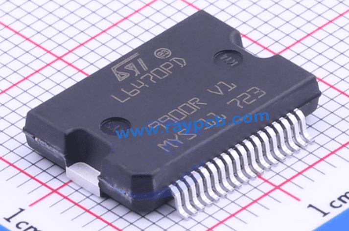
L6470PD is a fully integrated solution with a bipolar stepper motor. It is designed to work with the two-phase bipolar stepper motors with microstepping solutions.
In this article, you will realize how the mixed analog technology and other relevant solutions come together to make this one of the most dynamic bipolar stepper motors.
Balancing Power Performance and Temperature Usage
L6470PD also offers a balanced interfacing between the temperature and power usage. For example, the two levels of overtemperature protection are in place to prevent the IC from going above the recommended temperature rating.
On the other hand, it uses a programmable non-dissipative overcurrent protection. This solution helps to protect the IC and the target device from getting damaged when power supply is above or lower than the recommended rating.
The overcurrent protection takes precedence in the integration of a dual low RDS (on) DMOS full bridge. This full bridge paves the way for all the power switches to be equipped with an accurate on-chip/on-die current sensing circuitry. This circuitry is ideal for both use cases – protecting the IC from overcurrent and keeping the non-dissipative current control under effective management.
L6470PD also supports a variety of other enhanced circuit protective mechanisms, including:
- Motor stall
- Thermal protection
- Low bus voltage
These set of protective functions do not only keep the L6470PD safe over and undercurrent performances. The functions also come in handy for use with the most-demanding motor control applications.
Programmable Speed Profile
Speed is of the essence in a stepper motor’s function and we are glad to see it has been taken care of with L6470PD. In this regard, it offers a programmable speed profile
User-Defined Motion Profiles
Since L6470PD does more with motion detection, it makes sense to have facilities in place to make that work. That is the case with the user-defined motion profiles; a set of profiles designed to enable easy programming.
These profiles are programmable via a set of dedicated registers. They comprise the following:
- Deceleration
- Acceleration
- Speed position
- Target position
Excellent Command Management

To keep all the commands in one house and manage the same effectively; L6470PD uses a set of standard 5-Mbit/s SPI. Through this command manager, the other commands in the IC can be sent and processed in real-time.
The following can be sent through it:
- PWM frequency
- Current control value
- Deadtime
- Current protection trip point
Voltage Regulator
Besides having an excellent power management and SPI interface solutions; L6470PD also has an internal voltage regulator.
The regulator helps in coordinating the voltage within and inside the device. Here is a breakdown of how it works:
1. Voltage Stability
Regulating voltage is one thing and ensuring the voltage is stable is another. That is the reason behind the required connection of a 22µF between the ground and the VREG pin.
2. Voltage Generation and Distribution
L6470PD’s internal voltage regulator is not in function to the regulation of (excessive) voltage. It can also generate and distribute the same.
For voltage generation, it starts from any of the motor power suppliers (VSB or VSA) to generate up to 3-V voltage.
Then, for the voltage distribution, it supplies the VDD pin as a way of ensuring an excellent compatibility of the device’s digital output range to 3.3 volts.
The 5-voltage compatibility can also be obtained; only if the VDD pin is connected to an external 5-V voltage source.
3. Thermal Shutdown Capabilities
L6470PD also ensures that the thermal performance is top-notch, and that is the reason for the thermal shutdown capability.
It uses an internal sensor to monitor or regulate the thermal performance, with an emphasis on when it goes above. When this happens, this internal sensor would notify the TH_WRN bit located in the STATUS register. Upon getting the notification, the TH_WRN bit would be forced to operate “low,” pending when the accurate thermal performance is back.
At that point, the device is still at the warning mode tagged the Tj(WRN). As such, there is still a chance for the device to regulate the thermal performance and get back on track.
However, if the overloaded thermal performance continues to skyrocket, the device would continue to drop the thermal shutdown until it gets to the thermal shutdown threshold tagged Tj(OFF). At this point, the device would start the process of shutting down by activating the TH_SD bit in the STATUS register to be forced low. This signifies the relegation of the device into the thermal shutdown condition.
Product Attributes
Below are some of the attributes of this bipolar stepper motor:
| Attributes | Description |
| Operating Temperature | -40˚C to 150˚C |
| Motor Type – Stepper | Bipolar |
| Typical Application | General-purpose uses |
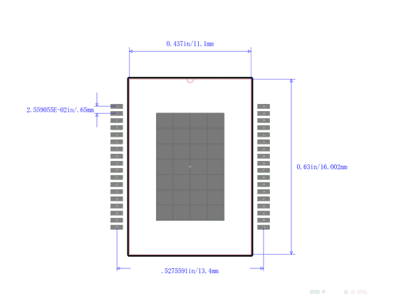
| Type of Mounting Style | Surface-mounted |
| Technology Used | DMOS |
| Voltage – Load | Between 8 volts and 45 volts |
| Typical Functions | Power Stage, Fully Integrated Driver and Control. |
| Type of Interface | SPI |
| Voltage – Supply | 3.3 volts and 5 volts |
| Output Configuration | Half Bridge (4) |
| Current – Output | 3A |
| Step Resolution | 1/128 |
L6470PD’s Design Iterations
Here are some of the additional configurations we think you should know about L6470PD’s bipolar stepper motor:
4. Microstep Resetting
L6470PD’s bipolar stepper motor can divide a step into 128 microsteps. However, there is a chance to reset these steps – via the step mode changing.
The idea is that once the step mode is changed, after bridges are disabled; it would be possible to reset. The resetting takes place because of the resetting to zero of the electrical position. The electrical position, in this instance, refers to the point of the generated microstepping sinewave.
5. Powering the Device
On power-end, the values of the target device are often reset to the default setting, typically involving the following values:
- Forced low for the LAG output.
- Default resetting of the registers.
- The UVLO bit in the STATUS register will get into the “fail condition,” which is the same thing as becoming “forced low.”
- Disabling of the High Z or Bridges.
On the other hand, when the device is about to power-up, the following will be in position:
- The internal oscillator becomes active.
- All the logic IOs and the power bridges in high impedances will be disabled.
Conclusion
L6470PD’s bipolar stepper motor offers a fully integrated solution with motor engine and SPI interface. This combination aids the manipulation of power from a particular source to related electrochemical actuato
