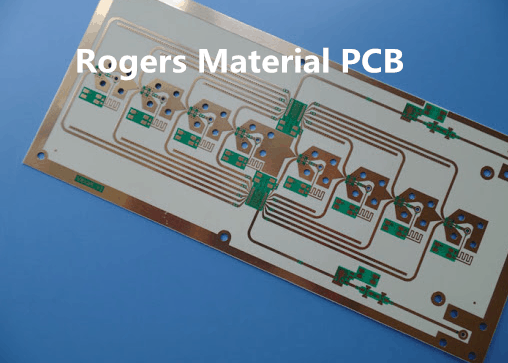
Rogers PCB is a RF pcb board that is produced by Rogers company’s raw material .
Rogers is a company that manufactures the laminate materials which is used for manufacture electronic circuit boards . Most PCBs are made of a material known as FR4 (Flame Retardant level 4), which is a composite of glass fiber/epoxy, with copper foil laminated on one or both sides. Rogers PCBs as compared to other standard PCB are seen to be quite different, because they have no glass fiber in the middle, and are ceramic-based.
Features
Some of the distinguishable features of Rogers PCB are given bellow. Rogers PCBs can be used for microwave point to point, RF identification tags, automotive radar and sensors, and power amplifiers.
- They are made up of woven glass reinforced hydrocarbon.
- Its electrical performance is like to that of PTFE
- Such PCB material have a thin layer for conduction
Rogers PCBs are available in different combination of material, which may be the different composition of laminated materials that are composed of woven glass-reinforced epoxy laminates, cross piled woven glass-reinforced laminates and PTFE ceramic laminates.
Thermoset Thermally & Electrically Conductive Adhesive (TECA) Film, Ceramic PTFE Bond ply, and Hydrocarbon are also used as bonding materials.
Why Rogers PCB material?
There are several reasons which gave the priority to roger material over other material and shows why Rogers PCBs are to be chose among other alternative. The reason behind it is That it shows best result in challenging environment, its quality and its use. Although rogers PCBs material have high prices as compared to others, but it can perform best at worse condition and have a lot of more advantages. As FR-4 material can provides the elementary standard for PCB substrates, keeping most effective stability between cost, durability, performance, production, as well as electrical properties. However, as performance and electrical properties have an important role in the designs, some feature of Rogers materials is given bellow which shows its importance over other material:
- Low electrical signal losses
- Cost-Effective PCB fabrication
- Low dielectric loss
- have high ability to thermal management
- The range of dielectric constant is wide and the DK values is in between 2.55-10.
- For space applications the outgassing is low
- It Improve impedance control
The difference between FR-4 material and Rogers material
The main difference between Rogers PCB and ordinary PCBs is their use, ordinary PCBs are limited for certain range of frequencies which is less than that of Rogers material. Rogers PCBs are mostly used in high frequencies applications purpose above 500 Mhz, while ordinary PCBs cannot be applicable to use them while if you are dealing with application using high frequencies.
The ideal PCB material should have the characteristics of zero moisture absorption when it is placed in liquid. Most of substance offer absorption value of in-between 0.01 percent and 0.20 percent. Absorption percentage has direct relation with thermal and electrical properties of the material Higher the absorption percentage, higher will be the influence on the thermal and electrical properties of material and will reduce performance and efficiency.
In comparison with ordinary PCBs Rogers PCBs have least absorption, thus Rogers PCBs are applicable to be used in difficult conditions and unstable environment. For example, Rogers PCBs can be used in aerospace and defense systems. While the other standard PCBs are more proper for low exhaust areas and uses such as standard switchboards.

Rogers and standard PCBs are also different in terms of the prices. Rogers is more expensive, considering their high quality. Rogers PCBs are expensive than other PCBs in cost while in performance Rogers material is best choice. The variation in price is due to quality and material used in it. The industry that the PCB targets is also a determinant of the cost.
- Rogers PCB material are higher in price as compared to FR4 material.
- Rogers material are the best performer when operating frequencies is high as compared to FR4 material.
- The dissipation factor DF of Rogers material is less so it has low electrical signal losses than that of FR4 material.
- Rogers material has a wide range of dielectric constant DK typically between 2.5 to 11 which increase its impedance stability while FR4 material has value of 4.5.
- Rogers material has a wide range of dielectric constant DK typically values between 2.5 to 11 while for FR-4 yield a Dk of about 4.5.
- Roger material shows less variation In thermal management than FR4 material.
Conclusion
If you are using PCB in space technology, mobile networking, microwave application then Rogers PCBs will give outstanding performance over any other PCBs. As rogers PCBs price is high compared to other PCBS but the improved performance and the extra abilities make it cheaper than others. Thus Rogers PCBs can be preferred over any other PCBs. Extensive businesses and organization in several industries give preference to Rogers PCBs because of it high performance and reliability. Thus while selecting PCB for your project it is required to know that how it is better than Rogers.
The Application of Rogers in PCB
Mostly in RF microwaves, high-speed designs, military, automotive industries, mobile application microwave point to point, RF identification tags, automotive radar and sensors uses Rogers material. Rogers PCB are hydrocarbon ceramic laminates and gave upper level ability to operate at high frequency, yield better result and reduced cost printed circuit fabrication which make it thermally stable and reduce the electrical losses (signal loss). standard epoxy/glass (FR-4) method is used for fabrication.
Dielectric material is used in Rogers material is used as an insulation layer which is a bad conductor of electricity, on the regular FR-4 based printed circuit boards. Here is some example of di-electric materials are Porcelain, mica, glass, plastics and some metal oxides are good dielectrics. The use of dielectric materials makes it possible to give it best properties like low di-electric loss, low signal loss, low cross-over and cross talks. The thickness of rogers material can be maintained up to o.1 mm which is quite compatible with over other substrate like FR-4. For different purpose of use and application Rogers PCBs are available in many different materials to cover such wide range of application. For improved performance and electrical effects, this article will help you that which material you have to select for your application by comparing these properties like low electrical signal loss, dielectric loss, cost circuit fabrication, and outgassing for space applications. Rogers dielectric PCB materials are best performing material for RF applications and mobile phone design. For designing of flexible PCBc Roger material is also used. RO4000 material have the properties required for the designers of RF microwave circuits and matching networks and controlled impedance transmission lines and offer a range of dielectric constants (2.55 – 6.15), are available with UL 94 V-0 flame retardant versions.
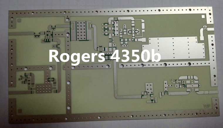
Rogers 4350b laminates are using the processing technique of regular glass/epoxy but with high control of dielectric constant, reduced electrical signal loss and high thermal stability. Such material is more effective in cost compared to conventional microwave laminates and doesn’t require any unique procedures and through-hole treatments.
Designing of Rogers PCB
The given bellow tips are helpful while designing performance-driven Rogers PCB. While dealing with high frequencies Rogers PCB give you flexibility to select different material components for the proposed design due to wide range of dk. Rogers Produce laminate materials which is used in production of printed circuit board. It is a best quality PCB material which provide an extended values for dielectric constants In wireless as well as in wire connected communication circuits the Dk is causing low signal loss. Rogers PCB give you comparatively superior thermal resistance in worse condition fast communication and application environments. As the number of electronic products increases exponentially, more attention is paid to technical problems. It is very easy to do circuit designing with Rogers 4350B for applications such as network matching and impedance controlling of transmission lines. We will be focusing more technallicy for designing high performance Rogers PCB.
Thermal Expansion Coefficient (CTE)
It is well known that most of the material expands as increase occur in the temperature of the substance and vice versa. Thus, the same also happen with the PCB material it also relaxed/expand as it is subjected to high temperature or decreasing temperature respectively. Usually, a temperature limit, also known as glass transition temperature, will define when the expansion will take place. The higher the glass transition temperature material, the higher will be in performance and quality, bellow transition temperature PCB material doesn’t expand while if the temperature increase cross over the threshold level then expansion will begin. Higher the coefficient of thermal expansion higher will be the resistance to deformation in shape of material. Thus, coefficient of thermal expansion has a relation with the deformation lower the value of CTE deformation will start earlier and will not be applicable to use at high temperature as it will deform and may cause malfunction or effect the result the unit of deformation is in parts per million also known as (ppm). Copper has the CTE value of 18 ppm which means that if one-degree raise occur over CTE will allow to relax the material by18 ppm. If the substrate and copper CTE mismatched it will arise the problem, as the CTE of substrate will be higher as compared to that of copper in per degree centigrade, causing the expansion of substrate material higher as compared to that of copper which may cause of de-lamination or solder joint failures. Normally we use a substrate material heaving value of CTE less than 70 parts per millions. Rogers 4000 PCB material’s coefficient of thermal expansion helps the designers with various advantages for example matching networks and its controlled impedance transmission lines. It is mostly similar to copper comparing in XY plane, which enable it to perform with extraordinary dimensional stability. Stability is a unique property which is important for fabrication of the dielectric multilayer PCB boards and applications which are sensitive to temperature variations.
Rogers’s material decreases the stresses which may result in the unintended change in the physical shape of PCB board which is a main advantage of such material. Such boards have a value glass transition temperature almost close to 280°C (536°F) so its expansion characteristics remain stable over the entire range of circuit processing temperatures. Thus, if your project is temperature sensitive and can be malfunctioned or interrupting result by change in temperature then Roger 4000 is the best choice for you.
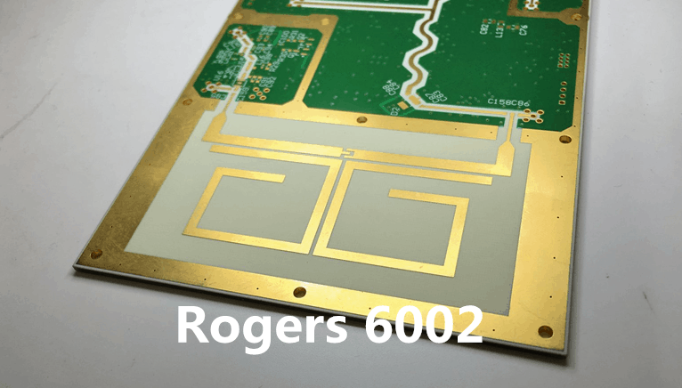
RT/duroid 6002 microwave material is one of the initial low loss and low dielectric constant laminate to offer high ranking electrical and mechanical properties required for the purpose of designing complex microwave structures which are mechanically good and electrically stable. The thermal coefficient of dielectric constant is extremely low from -55o C to+150o C (-67°F to 302°F) which help in the designing of filters, oscillators and delay lines the electrical stability needed in today’s demanding applications. Coefficient of thermal expansion (CTE) is low which ensures excellent reliability of plated through-holes. RT/duroid 6002 materials have been successfully thermally cycled (-55o C to 125o C [-67°F to 257°F]) for over 5000 cycles and have no single failure. The best dimensional stability (0.2 to 0.5 mils/inch) is obtained by resembling the X and Y coefficient of expansion to copper. Most ot the time it will remove double etching to achieve compact positional tolerances. The low tensile modulus (X,Y) greatly decrease the stress exerted on the solder joints and permit the expansion of the laminate to be constrained by a minimum amount of low CTE metal, (6 ppm/o C) further increasing surface mount reliability, ½ oz. to 2 oz./ft. 2 electrodeposited copper, ½ oz to 1 oz. reverse treated electrodeposited copper or ½ oz. to 2 oz./ ft.2 rolled copper may be point out cladding on dielectric thicknesses from (0.005” to 0.125”) (0.13mm to 3.18mm). RT/duroid 6002 laminate is also available in cladding of 2 layer aluminum, brass, or copper plates and resistive foils. Applications particularly suited to the unique properties of RT/duroid 6002 material include flat and non-planar structures such as antennas, complex multi-layer circuits with inter-layer connections, and microwave circuits for aerospace designs in unfriendly condition. RT/duroid 6002 laminates have Underwriters Laboratories recognition under classification 94V-0 (Vertical Flammability Test).
RO3000 series materials exhibit a coefficient of thermal expansion (CTE) in the X and Y axis of 17 ppm/°C. This expansion coefficient is like to that of copper, which improve the dimensional stability and reduces the tendency for bow and misshape. This matched expansion coefficient also remove the tendency for delamination for dumpy metal cladding. The Z-axis CTE is 24 ppm/°C, which supply unusual plated through-hole reliability, even in high critical thermal environments. RO3000 series laminates can be fabricated into PCBc by using ordinary PTFE circuit board processing techniques, with some modifications whose details is given in the application note “Fabrication Guidelines for RO3000 Series High Frequency Circuit Materials.”
Dielectric Constant
It can be defined as the ability of a material to store electric charge is known as dielectric constant or relative permittivity. If a material has a Greater the value of dielectric constant, will have high capacitance value and hence greater number of charges will be stored in the material which result to a high voltage appear across the PCB, it also helps in reducing the size of PCB. For a extend range of frequencies, the dielectric value is content due to which it can perform better in broad band application. While choosing a high frequency circuit board material one required to weighing some factors, including cost and performance. A main starting point in sorting through printed circuit board (PCB) materials is usually the dielectric constant Dk, one of the needed characteristics of a laminate material and one that is subject to many comparisons among different suppliers of PCB materials.
Electronic circuit which are operating at high-frequency need a constant and stable DK constant values over a wide range to make easier for selection of PCB material for designer. A material heaving high dielectric constant value will store large number of charges resulting higher voltage and capacitance. Rogers’s PCB material can be operated at wide range of frequencies with a constant value of dk, thus for broadband purpose and applications Rogers material is a best choice. The dielectric constant of Rogers PCB also have relatively small values of temperature coefficient, due to which it can be prioritize for using in temperature-sensitive devices. The dielectric constant of Rogers 4350b is 3.66 which makes it ideal for connection between two points in microwave application.
At high frequencies, RO4000® hydrocarbon ceramic laminates are designed to achieve better performance. It is a low-cost circuit fabrication, and low loss material which can be fabricated using ordinary epoxy/glass (FR-4) processes. If we are dealing with the frequency range greater than 500 MHz, the ordinary will be limited to this operation thus it will narrow down the choices of laminates material available to designers. RO4000 material is the best fit for applications of RF microwave circuits and matching networks and controlled impedance transmission lines. Low dielectric loss RO4000 series materials should be used in various applications where higher operating frequencies restrict the use of common circuit board laminates. It has the lowest temperature coefficient of dielectric constant compared to conventional PCB material, and the value of dk is stable over a wide range of frequencies. RO4000 LoPro laminate which is latest version of the RO4000 resin system to bond reverse treated foil. Values mentioned earlier are RO4000 laminates without the addition of the LoPro resin. For double-sided PCB boards, the LoPro foil yields increase in the thickness of approximately 0.0007” (18mm) and its Dk is close to 2.4. As the core thickness decreases from 0.020” to 0.004 the Dk reduced up to 0.1.
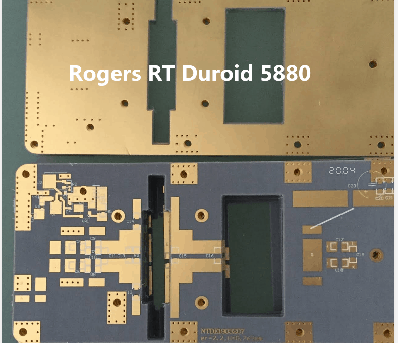
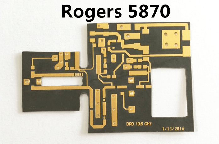
Rogers 3003, RT5880 and RT 5870 are the best performance material among other PCB materials which can perform better in the applications operating at high frequency, high speed performance in both wired and wireless communication and noise sensitive circuits. The working frequency range and dielectric constant of all the materials is given bellow in the table which make it easier for designer to select the best material to be used for the desired application.
| Material | Dielectric Constant | Frequency Range | Applications |
| R3003 | 3.00 | 8 GHz- 40 GHz | · Automotive Radar · GPS Antennas |
| R4350B | 3.66 | 8 GHz- 40 GHz | · Cellular Base Station antennas · Microwave point to point links |
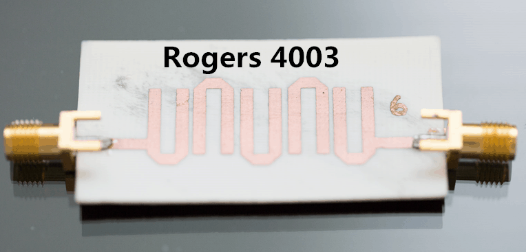
| R4003C | 3.55 | 8 GHz – 40 GHz | · RF identification tags · Automotive radars and sensors |
| RT5880 | 2.20 | 8 GHz – 40 GHz | · Commercial airline broadband antennas · Military radar systems |
| RT 5870 | 2.33 | 8 GHz – 40 GHz | · Missile Guidance Systems · Microstrip and Strapline circuits |
All the above material given in the table are tested by the differential phase length method with in the frequency ranges from 8 MHz to 40 MHz. there is a slight variation in the dielectric constant value with a 10GHz change in frequency.
Hygroscopic
Moisture should not be adsorbed by PCB materials from the environment under conditions which is not practically possible. Rogers PCB like every other element absorbs moister. The moisture absorption rate of many current PCB materials has values of in-between 0.01 to 0.2 percent. Thus, it is required for PCB material to have low hygroscopic. If the absorption rate is higher it will influence more on the thermal and electrical properties of material. The moisture absorption rate of rogers PCB is lower than the conventional PCBs resulting in better electrical as well as thermal characteristics. Hence, it can be used for all kinds of conditions and environments without any decay in performance. Additionally, such PCBs have less chances of failures. The theoretical values for the Rogers 4350b has almost that of 0.06.
TemperatureProblems
The project domain defines the range of operating temperature at which the PCB board material required for an application. If the electronics parts of the product are sensitive to higher temperatures, the designer should select a suitiable Rogers PCB. If temperature rises above certain allowable level, the PCB need to have a mechanism which can reverse such variations. If temperature issues is not taken into consideration, and operate above temperature range will lose some mass and would decay with the passage of time. Most of the applications demand the safe range of temperature as high as 350 degrees Celsius. Some rogers’ material has high decomposition temperature as compared to the conventional PCB materials therefore the designer should select this material for various applications.
DesignRequirements for DriverCircuit
Designing of driver circuit usually require stable impedance. The dielectric constant values range of Rogers material is wider than the FR-4 material. Hence, the impedance is kept stable and the performance is increased for such type of circuit designs. Usually circuits operation at high-frequency perform operation at the characteristic impedance value of 50Ω which should match with the other components of circuit in order to ensures the maximum power transfer between input and output additionally the circuits should not develop a lot of standing waves, so that there will be no reflection from the load.
Many software tools like computer-aided-engineering permit us to choose various important specification for Rogers PCB design material. Using such tools one can select roger material of the desired dielectric constant, thus ensuring stability and impedance matching.
Conductivity
Some factors like dissipation factor should not be ignored by the engineers while choosing PCB materials and must take into consideration the other important properties of the materials like the power loss for the material which increases with increase in the operating frequency. Another important property is Thermal Conductivitywhich determine us about the heat conductive properties of the material. Consider the case of amplifiers or missile guidance systems, if heat is not properly managed it can cause mechanical and electrical variations in the properties of PCB material which can malfunction or lead to serious problems.
Rogers PCB Application
- Lower cost and large batch
Roger PCB material like high-frequency materials have comparatively least cost and permit number of bands for PCB materials. Generally, it is used in radar sensors applications. It has a hybrid PCB which utilize materials composition with multiple coated flame-retardant standard FR-4 substance material. Additionally, the glass-transition temperature denoted by (Tg) has a high value of. Also, it consist of a single coat of PCB material which is used in high-frequency applications.
Such composition of PCB materials is necessary for maintaining reliability and controlling cost and resulting in an increased electrical performance. 77 GHz frequency is required in the radar sensors for certain specific performance requirement. Thus, for outer layer roger materials are mostly used for high-frequency devices designs. This material has the required properties necessary for outstanding performance at millimeter-wave as well as for microwave frequencies.
- High performance and small size
In electronics, the design of an efficient power amplifier is very critical. The PCB board material of an efficient amplifier circuit should have the necessary properties that would assure high amplifying performance of the design. Rogers PCB which is mostly used in high-power amplifying purpose. In order to get high performance from the power amplifier the heat must sink away from transistors. It has a better coefficient of thermal expansion and thermal conductivity which is discussed already. Additionally, it will also extend the life time of speakers. Thermal conductivity is defined as the amount of power in watt required for meter of substance per degree Celsius. Hence, Rogers PCB is one of the best PCB materials for many modern applications.
The thermal conductivity of Rogers 4360b and Rogers 4360 laminate material is 0.62 and 0.8 Watt per meter per kelvin respectively. The higher the thermal conductivity of the laminate the higher the capability to handle higher power.
The Significance of Physical Parameters
Besides the factors already discussed, the quality of hole is another critical factor in selection of a proper PCB material. Besides Rogers 4350 PCB material has one of the best hole quality, still one would need to ensure the drills in PCB are done relative to the epoxy/glass standards. As compared with epoxy/glass, the irregularity in holes does not vary with the passage of time as compared to the conventional materials. The drilling range of variables offered by it is very wide. So, it is advised not to increase the speed of drilling above certain threshold value.
Another parameter which has a wide impact is Rogers PCB is metal deposition which is as important as the previously discussed. Before metallization electro-less copper processing in addition to no particular preparations is also supported by Rogers 4835b and 4835. The ionic and colloidal conductive layers are also deposited directly.
In next article,We will talk Rogers pcb assembly,What ‘s difference rogers pcb assembly with fr4 pcb assembly.
