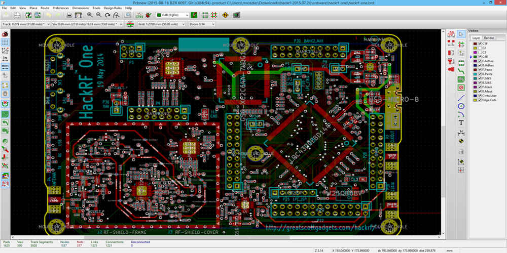
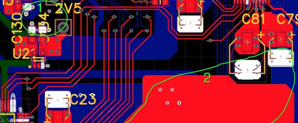
Layout driver power amplifiers, also known as LDMOS amplifiers, are essential components in modern RF power amplifiers. These amplifiers are used in a wide range of applications, including cellular base stations, wireless infrastructure, and broadcast transmitters. The layout of these amplifiers is critical to their performance, and designers must carefully consider a variety of factors when designing the layout of an LDMOS amplifier.
One of the primary considerations when designing the layout of an LDMOS amplifier is thermal management. These amplifiers generate a significant amount of heat, and if not properly managed, this heat can damage the amplifier or surrounding components. Designers must carefully consider the placement of heatsinks, thermal vias, and other cooling components to ensure that the amplifier operates within safe temperature limits. Additionally, designers must consider the layout of the amplifier’s power supply and control circuitry to minimize heat generation and ensure reliable operation.
Another important consideration when designing the layout of an LDMOS amplifier is RF performance. The layout of the amplifier can have a significant impact on its RF performance, including its gain, linearity, and efficiency. Designers must carefully consider the placement of RF components, such as matching networks and filters, to ensure that the amplifier meets its performance specifications. Additionally, the layout of the amplifier’s input and output ports can have a significant impact on its RF performance, and designers must carefully consider the placement of these ports to minimize losses and reflections.

Overview
What is a Layout Driver Power Amplifier?
A Layout Driver Power Amplifier (LDPA) is a type of amplifier used in wireless communication systems. It is designed to amplify the signal from the baseband processor to the power amplifier, which in turn drives the antenna. The LDPA is responsible for maintaining the signal quality and ensuring that the signal is transmitted at the correct power level.
The LDPA is an essential component in wireless communication systems, as it is responsible for driving the power amplifier. The LDPA ensures that the power amplifier receives a clean and stable signal, which is critical for maintaining the signal quality and avoiding distortion.
Applications
The LDPA is used in a wide range of wireless communication systems, including cellular networks, satellite communication systems, and wireless local area networks (WLANs). The LDPA is an essential component in these systems, as it ensures that the signal is transmitted at the correct power level and maintains the signal quality.
The LDPA is also used in other applications, such as radio frequency identification (RFID) systems, where it is used to amplify the signal from the reader to the tag. The LDPA is also used in medical devices, such as implantable devices, where it is used to amplify the signal from the sensor to the external device.
In summary, the LDPA is a critical component in wireless communication systems, ensuring that the signal is transmitted at the correct power level and maintaining the signal quality. It is used in a wide range of applications and is an essential component in modern communication systems.
Design Considerations

Power Dissipation
One of the most critical aspects of designing a layout driver power amplifier is power dissipation. The amplifier must be able to handle the power dissipated in the output transistors without overheating. This requires careful selection of the transistors, as well as the use of heat sinks and thermal management techniques.
Maximum Output Power
The maximum output power of the amplifier is another crucial consideration. The power amplifier must be able to deliver the required output power without distortion or clipping. This requires careful selection of the output transistors and the design of the output stage.
Efficiency
Efficiency is a critical factor in power amplifier design. The efficiency of the amplifier determines how much power is wasted as heat and how much is delivered to the load. A high-efficiency amplifier is essential for battery-powered applications.
Input and Output Impedance
The input and output impedance of the amplifier must be carefully matched to the source and load impedance, respectively. This requires careful selection of the input and output coupling components, as well as the design of the input and output stages.
Frequency Response
The frequency response of the amplifier must be flat over the required bandwidth. This requires careful selection of the gain and compensation components, as well as the design of the feedback loop.
In summary, designing a layout driver power amplifier requires careful consideration of power dissipation, maximum output power, efficiency, input and output impedance, and frequency response. By carefully selecting components and designing the amplifier stages, it is possible to achieve a high-performance amplifier that meets the requirements of the application.
Circuit Topologies
Class A
Class A is the simplest and most linear amplifier topology. It is also the least efficient. In a Class A amplifier, the output device(s) are always on and conducting current, even when there is no input signal. This results in a lot of power being wasted as heat. Class A amplifiers are used where the highest quality audio is required, such as in high-end hi-fi systems and professional audio equipment.
Class AB
Class AB is a compromise between Class A and Class B. In a Class AB amplifier, the output device(s) only conduct current when there is a signal present. This reduces the amount of power wasted as heat compared to a Class A amplifier. Class AB amplifiers are used in a wide range of applications, from car audio systems to home theater systems.
Class D
Class D is the most efficient amplifier topology. In a Class D amplifier, the output device(s) switch on and off rapidly, creating a high-frequency pulse train that is filtered to produce the output signal. This results in very little power being wasted as heat, but can introduce distortion if not implemented properly. Class D amplifiers are used in a wide range of applications, from portable audio devices to high-power subwoofers.
Each of these amplifier topologies has its own advantages and disadvantages, and the choice of topology depends on the specific requirements of the application.
Performance Metrics

Power Added Efficiency
Power Added Efficiency (PAE) is a measure of how efficiently a layout driver power amplifier converts DC power into RF power. It is calculated as the ratio of the RF power output to the total DC power consumption of the amplifier. Higher PAE values indicate that the amplifier is more efficient in converting DC power to RF power.
Linearity
Linearity is a measure of how well the amplifier maintains the linearity of the input signal at the output. A linear amplifier produces an output signal that is a scaled version of the input signal. Non-linear amplifiers, on the other hand, produce an output signal that is a distorted version of the input signal. The linearity of an amplifier is typically measured using the Intermodulation Distortion (IMD) test.
Noise Figure
Noise Figure (NF) is a measure of the amount of noise that an amplifier adds to the input signal. It is defined as the ratio of the output noise power to the input noise power. A lower NF value indicates that the amplifier adds less noise to the input signal.
Harmonic Distortion
Harmonic Distortion (HD) is a measure of the amount of harmonic content in the output signal. Harmonic distortion occurs when the amplifier produces output signals that are multiples of the input signal frequency. A high HD value indicates that the amplifier produces a significant amount of harmonic distortion.
In conclusion, the performance of a layout driver power amplifier can be evaluated using several metrics, including PAE, linearity, NF, and HD. A good amplifier should have high PAE, low NF, low HD, and good linearity.
Conclusion
In conclusion, the layout of a driver power amplifier is an essential factor that affects the performance of the amplifier. The layout should be designed to minimize parasitic elements and ensure proper grounding to avoid noise and distortion.
The use of proper layout techniques such as the use of ground planes, bypass capacitors, and proper placement of components can significantly improve the performance of the amplifier. It is also important to consider the thermal management of the amplifier to ensure that it operates within safe temperature limits.
In addition, the use of simulation tools such as SPICE can aid in the design and optimization of the amplifier layout. These tools can help in identifying potential issues and fine-tuning the layout to achieve optimal performance.
Overall, a well-designed layout is crucial to achieving high-performance driver power amplifiers. By following proper layout techniques and utilizing simulation tools, designers can ensure that their amplifiers meet the desired performance specifications.

