Arduino has provided the platform upon which a wide range of electronic projects can be customized. Today, you can leverage this platform to build an ultrasonic sensor.
This is a definitive guide of what the Arduino ultrasonic sensor project is all about.
What is Arduino?
Let us start by understanding the workings of the platform. Arduino is an open-source electronics (development) platform that seeks to simplify the configuration of electronic items by offering easy-to-use hardware and software.
Through this platform, you will have access to a wide range of tools, including the Arduino programming language and the Arduino boards.
What is an Ultrasonic Sensor?
Before committing to using Arduino for an ultrasonic sensor project, it is imperative to understand the basis of the project.
Ultrasonic sensor helps to detect ultrasound. Ultrasound, on the other hand, has to do with the pitch of a sound, which is usually higher than the human sound.
Thus, ultrasound has to do with a high-pitched sound wave that is typically louder or higher than the frequency of sound heard by human beings.
Ordinarily, it wouldn’t have been possible for human beings to pick out such sounds, because of the speed at which they travel. But with the aid of the ultrasonic sensor, it becomes easier to “listen to the sound” despite the speed.
How Ultrasound Compares to Human-Heard Sounds
Besides the speed at which ultrasound (high-pitched sound wave) travels, there are also a couple of factors that differentiate and make it better than the sounds heard by human beings.
These are some of the unique features:
- Sound Varieties: ultrasound is able to “listen to” or “hear” sounds of different ranges. For example, it is possible to hear a deep rumbling noise and a high-pitched whistle.
- Peculiarity: the peculiarity of ultrasound stems from the fact that it has a frequency that typically exceeds 20,000 Hz. This makes it hard for human beings to typically listen to the sound wave as it passes.
Getting Started with Your Arduino Ultrasonic Sensor Project
There are a couple of factors worth considering when choosing an Arduino ultrasonic sonic. One of such factors is the extent it goes to determine the sound wave.
With this and several other factors, it is not surprising that most hobbyists settle for the HC-SR04 ultrasonic sensor.
Here are some of the reasons why this is a better choice:
Excellent Distance Measurement
One of the core ways that an ultrasonic sensor can determine the extent of the sound wave is by measuring the length of the sound.
Thus, the ultrasonic sensor called the HC-SR04 meets that need, because of the excellent distance measurement capabilities. It uses SONAR for this purpose. When determining the distance of the sound, the SONAR also focuses on the high accuracy and stable readings. This way, the accurate sound wave would be described.
A Wider Range
The (measuring) range of the SONAR is between 2cm and 400cm, which translates to about an inch to 13-feet.
It is pertinent to point out that the wider range of sound wave readings is also accentuated by the accuracy rate of 0.1-inches or 0.3cm.
The accuracy is nice, but there is one additional feature that makes it all worthwhile. The HC-SR04 ultrasonic sensor uses a non-contact range detection, which helps to keep the sound wave readings accurate, as the sensor is not restricted or subject to getting into contact with any other thing, but the sound wave.
Properties of the Arduino HC-SR04 Ultrasonic Sensor

The sensor doesn’t work alone. A lot of properties that come with help to enhance the performance. Let us start by dissecting the properties before we go into the overall functions.
Generally, it is composed of two (2) ultrasonic transducers. One of these transducers works as a transmitter. By this designation, the work of the transmitter is to transmit or to convert the output of the ultrasonic sound pulses, which is the same as converting the electrical signal. The conversion is done by converting the electrical signal into the corresponding 40 KHz ultrasonic sound pulses.
On the other hand, we have the other transducer working as a receiver. The work of the receiver (which is the SONAR that the HR-SR04 ultrasonic sensor uses), is to receive and listen for the transmitted pulses/reflected waves.
Now, it is the duty of the receiving transducer to take the functions of the ultrasonic sensor to the next level. Ideally, this happens when the receiving transducer, on receipt of the reflected waves, produces an output pulse, whose width is proportional or at par with the distance of the object in the front.
Technical Specifications of the Arduino HC-SR04 Ultrasonic Sensor
Here is a table representing the different technical specifications or attributes of the Arduino HC-SR04 ultrasonic sensor:
| Attributes | Specifications |
| Operating Voltage/Power Supply | +5V DC |
| Operating Current | 15mA |
| Operating Frequency | 40 KHz |
| Minimum Ranging Distance | 2 cm or 1-inch |
| Maximum Range | 400cm or 13-feet |
| Ranging Accuracy | 3mm |
| Measuring Angle | 15 degrees |
| Trigger Input Signal | 10µS TTL pulse |
| Echo Output Signal | The TTL pulse is proportional to the distance range. |
| Dimension | 45mm x 20mm x 15mm |
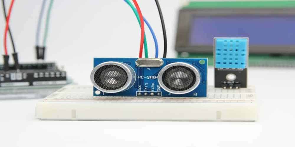
Arduino HC-SR04 Ultrasonic Sound Pinout
Let us quickly talk about the pinout specifications of this ultrasonic sound. Here are the four (4) pins used on the sensor and how they work, individually:
- VCC: this is the pin that powers the sensor. You can also call it the power pin. It is rated 5V, because it can be connected to the 5V output from your Arduino.
- Trig: this is the trigger pin. It is the pinout used to trigger or activate the ultrasonic sound pulses on the sensor. It is important to mention that the trig pin becomes active when it is set to HIGH for µS – which facilitates the ultrasonic burst.
- Echo: this is the third pinout of the Arduino HC-SR04 ultrasonic sensor. It is responsible for listening for the reflected signal after the Trig pin sends ultrasonic wave from the transmitter. Additional information about the Echo pin includes that the pin goes high as soon as the ultrasonic wave/burst is transmitted by the Trig pin. It still maintains the high state, and only goes low after the sensor receives an echo.
- Ground: the ground (GND) is the last pinout of the HC-SR04 ultrasonic sensor. It is meant to be connected to the ground or bottom part of the Arduino.
How the HC-SR04 Ultrasonic Sensor Measures the Distance of Sound
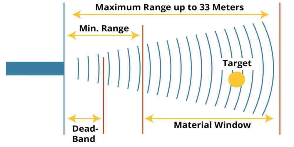
The simplest explanation is that the distance of the sound is determined or measured by the time differences between the moment the Echo pin goes high and when it goes low.
Thus, the calculation would be something like speed multiplied by time equals the distance.
However, there are a couple of other factors that help in finding out just the accurate distance of the sound wave.
Ultrasound Travel
The first thing is for the ultrasonic sensor to send out the ultrasound at 40,000 Hz. This ultrasound travels through the air away from the transmitter and only bounces back or returns to the original state when it encounters either an obstacle or an object on the pathway.
It is then important to pay attention to the difference in the time of ultrasound travel and when it bounces or returns to the module, as that gives an idea of what the distance is like.
Sound Generation via the Trig Pin
To get the accurate measurement, we have to use the Trigger pin. The standard is to make a setting of the Trig pin to a HIGH State for 10 µS. By this setting, the sensor sends out an 8-cycle ultrasonic burst pattern that travels at the speed of sound at 40 KHz.
One of the primary reasons for setting the Trig pin in this HIGH State is to enable the Echo pin to start waiting for the wave to be reflected on an object. It also helps the receiver (the Echo pin) to clearly differentiate the transmitted pulses from the ambient ultrasonic noise.
Echo Pin Timeout
The Echo pin has a timeout of 38 milliseconds or 38ms. What this means is that within 38 milliseconds, the Echo pin expects to have had the pulses reflected back, as a result of an object obstruction.
However, if this doesn’t happen, it indicates that the pathway is free, since there is no obstruction within the ultrasonic sensor’s range.
Therefore, the Echo pin’s signal will timeout or expire after the standard 38 milliseconds (38ms). When this happens, the echo signal will go low.
Note: the above summation is for determining the clear pathway for the Echo pin. However, what happens if there is an obstruction on the pathway?
If that were to be case, what the Echo pin would do is to go down sooner than the standard 38 milliseconds, and this is because it encountered or was obstructed by a reflected pulse.
Since the 38ms, which could have been the standard measurement is now reduced, you can get the right measurement with this formula: distance = speed x time.
Final Thoughts
When working on an Arduino ultrasonic sensor project, it is important to make the right connection. The connection includes placing the HC-SR04 ultrasonic sensor on the breadboard. You would then connect the VCC (sensor power pin) to the 5V pin on the Arduino’s output, as well as to the Ground (GND) pinout. The next process is to connect the Trigger (Trig) and Echo pins to the 9 and 10 digital pins.
For the best results, use the following components for the project – Arduino UNO starter board/kit, a breadboard, the HC-SR04 ultrasonic sensor and jumper wires.
