Digital logic is the foundation of modern computing, and Morris Mano is one of the most respected authorities on the subject. His book, “Digital Logic and Computer Design,” has been a standard textbook in electrical engineering and computer science courses for decades. In this article, we will explore the history and impact of Mano’s work on digital logic.
Morris Mano was born in 1932 in India and received his education in electrical engineering at the Indian Institute of Technology and the University of California, Berkeley. He began his career as a professor at the University of Massachusetts, Amherst, where he taught for over 30 years. During this time, he authored several textbooks on digital logic, including “Digital Design” and “Computer Engineering: Hardware Design.” However, it is his book “Digital Logic and Computer Design” that has had the most significant impact on the field.
Overview
Digital logic is a fundamental concept in computer science and electrical engineering. It involves the design and analysis of digital circuits that can perform logical operations. In this section, we will provide an overview of digital logic, including its definition, history, and applications.
What is Digital Logic?
Digital logic is the study of digital circuits that perform logical operations. These circuits are composed of basic building blocks called logic gates, which take one or more binary inputs and produce a binary output based on a predefined truth table. The most common logic gates are AND, OR, NOT, XOR, and NAND.
Digital circuits are used in a wide range of applications, including computers, telecommunications, control systems, and consumer electronics. They are also used in the design of integrated circuits, which are the building blocks of modern electronics.
History of Digital Logic
The history of digital logic can be traced back to the mid-19th century, when George Boole developed a mathematical system for symbolic logic. This system, known as Boolean algebra, provided a way to represent logical operations using algebraic symbols. In the early 20th century, Claude Shannon applied Boolean algebra to the design of digital circuits, laying the groundwork for modern digital logic.
The development of digital logic continued throughout the 20th century, with the invention of the transistor in 1947 and the subsequent development of integrated circuits. These advancements made it possible to design complex digital circuits that could perform a wide range of logical operations.
Applications of Digital Logic
Digital logic is used in a wide range of applications, including:
-
Computers: Digital circuits are used in the design of computer processors, memory, and input/output devices.
-
Telecommunications: Digital circuits are used in the design of communication systems, including modems, routers, and switches.
-
Control systems: Digital circuits are used in the design of control systems, including automotive systems, industrial automation, and robotics.
-
Consumer electronics: Digital circuits are used in the design of consumer electronics, including televisions, DVD players, and digital cameras.
In conclusion, digital logic is a fundamental concept in computer science and electrical engineering. It involves the design and analysis of digital circuits that can perform logical operations. Digital logic has a rich history, and it is used in a wide range of applications, from computers to consumer electronics.
Digital Logic Gates

Digital logic gates are the fundamental building blocks of digital circuits. They are electronic devices that perform logical operations on one or more binary inputs and produce a single binary output. There are three basic types of digital logic gates: AND, OR, and NOT gates.
AND Gate
The AND gate is a two-input gate that produces a high output only when both of its inputs are high. Otherwise, the output is low. The truth table for an AND gate is as follows:
| Input A | Input B | Output |
|---|---|---|
| 0 | 0 | 0 |
| 0 | 1 | 0 |
| 1 | 0 | 0 |
| 1 | 1 | 1 |
OR Gate
The OR gate is a two-input gate that produces a high output when either one or both of its inputs are high. The output is low only when both inputs are low. The truth table for an OR gate is as follows:
| Input A | Input B | Output |
|---|---|---|
| 0 | 0 | 0 |
| 0 | 1 | 1 |
| 1 | 0 | 1 |
| 1 | 1 | 1 |
NOT Gate
The NOT gate is a one-input gate that produces the opposite of its input. If the input is high, the output is low, and if the input is low, the output is high. The truth table for a NOT gate is as follows:
| Input | Output |
|---|---|
| 0 | 1 |
| 1 | 0 |
Digital logic gates are the basic building blocks of digital circuits, and they are used to implement complex digital systems. By combining these gates in various ways, it is possible to create circuits that perform arithmetic and logical operations, store and retrieve data, and control the behavior of other electronic devices.
Boolean Algebra
Basic Operators
Boolean Algebra is a branch of algebra that deals with binary variables and logic operations. It is a fundamental concept in digital logic design. The basic operators of Boolean Algebra are AND, OR, and NOT.
The AND operator returns true only if both input variables are true. The OR operator returns true if either of the input variables is true. The NOT operator, also called the complement operator, returns the opposite value of the input variable.
Laws of Boolean Algebra
The laws of Boolean Algebra are a set of rules that govern the manipulation of Boolean expressions. These laws help simplify complex Boolean expressions and make them easier to understand.
- Commutative Law: The order of the operands does not matter in an AND or an OR operation. A ∨ B = B ∨ A and A ∧ B = B ∧ A.
- Associative Law: The grouping of operands does not matter in an AND or an OR operation. (A ∨ B) ∨ C = A ∨ (B ∨ C) and (A ∧ B) ∧ C = A ∧ (B ∧ C).
- Distributive Law: The AND and OR operations can be distributed over each other. A ∨ (B ∧ C) = (A ∨ B) ∧ (A ∨ C) and A ∧ (B ∨ C) = (A ∧ B) ∨ (A ∧ C).
- Identity Law: The AND operation with 1 or the OR operation with 0 does not change the value of the other operand. A ∧ 1 = A and A ∨ 0 = A.
- Complement Law: The complement of a variable is the opposite value of the variable. A ∧ ¬A = 0 and A ∨ ¬A = 1.
Karnaugh Maps
Karnaugh Maps, also known as K-Maps, are a graphical representation of Boolean expressions. They help simplify complex Boolean expressions and minimize the number of logic gates required to implement the expression.
K-Maps are constructed by arranging the input variables in a grid and marking the cells that correspond to the true output values. Adjacent cells with the same output value are grouped together to form a simplified expression.
K-Maps are a useful tool for digital logic designers and can greatly simplify the design process.
Combinational Logic Circuits

Combinational logic circuits are digital circuits that produce an output based solely on the input. These circuits do not have any memory elements, and the output depends only on the current input. Morris Mano, in his book “Digital Design,” explains the various types of combinational logic circuits, including adders and subtractors, multiplexers and demultiplexers, encoders and decoders.
Adders and Subtractors
Adders and subtractors are used to perform arithmetic operations on binary numbers. An adder circuit takes two binary numbers as input and produces their sum as output. A subtractor circuit takes two binary numbers as input and produces their difference as output. The most commonly used adder is the full adder, which adds two binary digits and a carry-in bit to produce a sum and a carry-out bit.
Multiplexers and Demultiplexers
Multiplexers and demultiplexers are used to select one of several inputs and route it to a single output. A multiplexer takes multiple input lines and a select line as input and outputs the selected input line. A demultiplexer takes a single input line and a select line as input and outputs the selected output line. Multiplexers and demultiplexers are often used in digital communication systems to transmit multiple signals over a single channel.
Encoders and Decoders
Encoders and decoders are used to convert between different data formats. An encoder takes multiple input lines and produces a single output line that represents the input. A decoder takes a single input line and produces multiple output lines that represent the input. Encoders and decoders are often used in digital communication systems to compress and decompress data.
In summary, combinational logic circuits are essential building blocks in digital systems. Adders and subtractors, multiplexers and demultiplexers, encoders and decoders are some of the commonly used combinational logic circuits. Understanding these circuits is crucial for designing and implementing digital systems.
Sequential Logic Circuits
Sequential logic circuits are digital circuits that depend on the present state of the circuit to determine its future state. In other words, the output of a sequential logic circuit is not only dependent on the present input but also on the previous input and the current state of the circuit.
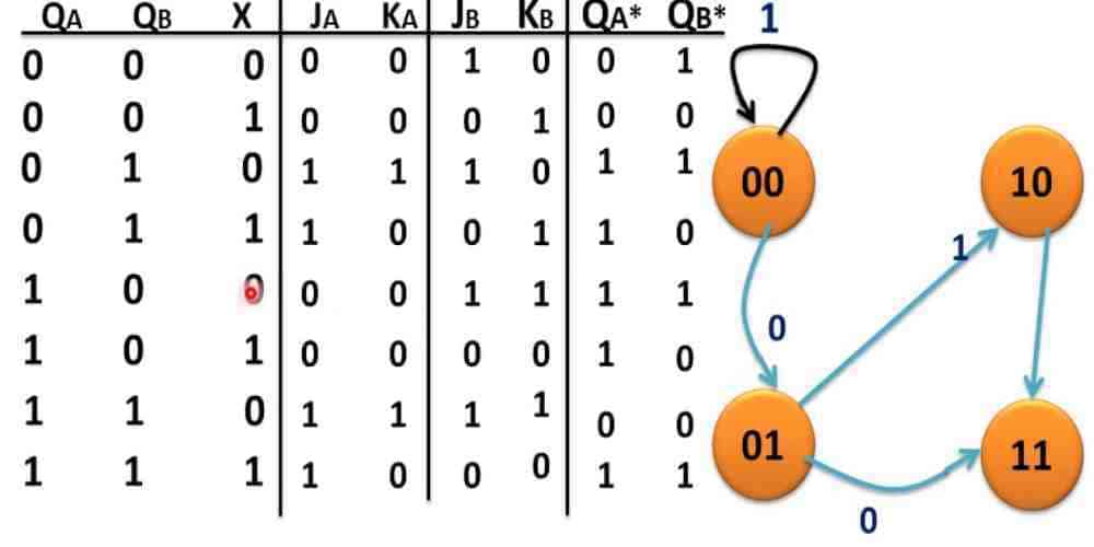
Flip-Flops
Flip-flops are the basic building blocks of sequential logic circuits. They are bistable circuits that can store one bit of information. The output of a flip-flop can either be a logic high or a logic low, depending on the input. The two most common types of flip-flops are D flip-flop and JK flip-flop.
Registers
Registers are sequential logic circuits that are used to store multiple bits of data. A register is made up of several flip-flops, and each flip-flop can store one bit of data. Registers are commonly used in digital systems for storing data temporarily or for shifting data from one location to another.
Counters
Counters are sequential logic circuits that are used to count the number of clock pulses or events. There are two types of counters: synchronous and asynchronous. Synchronous counters use a common clock signal to synchronize the operation of all flip-flops, while asynchronous counters do not use a common clock signal. Counters are commonly used in digital systems for applications such as frequency division, time delay generation, and event counting.
In conclusion, sequential logic circuits are an essential part of digital systems, and understanding their operation is crucial for designing and analyzing digital circuits. Flip-flops, registers, and counters are the fundamental building blocks of sequential logic circuits and are widely used in digital systems for various applications.
Digital Design
Design Process
Digital design is the process of creating digital circuits that can perform various logical functions. The design process involves several stages, including specification, design, simulation, and verification. The specification stage involves defining the requirements for the circuit, such as its functionality, performance, and power consumption. The design stage involves creating a high-level representation of the circuit using a hardware description language. The simulation stage involves verifying the functionality of the circuit using software tools. Finally, the verification stage involves testing the circuit using hardware tools to ensure that it meets the specifications.
Hardware Description Languages
Hardware description languages (HDLs) are used to describe digital circuits at a high level of abstraction. HDLs allow designers to create complex circuits using a set of predefined building blocks such as gates, flip-flops, and multiplexers. HDLs are used to create a design that can be simulated and verified before being implemented in hardware. Some popular HDLs include Verilog and VHDL.
Simulation and Verification
Simulation is the process of testing the functionality of a digital circuit using software tools. Simulation allows designers to test their designs before they are implemented in hardware, which can save time and money. Verification is the process of testing the circuit using hardware tools to ensure that it meets the specifications. Verification is a crucial step in the design process to ensure that the circuit functions correctly and meets the requirements.
In conclusion, digital design is a complex process that involves several stages, including specification, design, simulation, and verification. Hardware description languages are used to describe digital circuits, and simulation and verification are essential steps in the design process. By following a rigorous design process, designers can create digital circuits that meet the specifications and perform the desired functions.
