PCB soft start is a crucial aspect of electronic circuit design. It is a method of gradually increasing the voltage and current in a circuit to avoid sudden spikes that can damage components. Soft start circuits are commonly used in power supplies, motor control circuits, and audio amplifiers to limit the inrush current and extend the life of the components.
The soft start circuit is designed to limit the initial current surge that occurs when the circuit is turned on. This surge can cause damage to the components, especially if they are not designed to handle high current. By gradually increasing the voltage and current, the soft start circuit protects the components and extends their life. The soft start circuit can be designed using various components such as resistors, capacitors, and transistors, depending on the application and the desired performance.
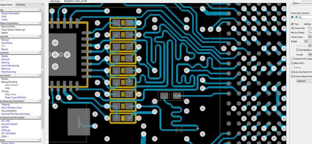
Layout for PCB Soft Start
When designing a PCB soft start, proper layout is crucial for its performance and reliability. In this section, we will discuss the key considerations for the placement of components, routing of traces, grounding, and decoupling.
Placement of Components
The placement of components in a soft start circuit is critical to ensure proper operation and avoid issues such as noise and interference. Here are some guidelines to follow:
- Place the MOSFET, diode, and inductor as close as possible to each other to minimize parasitic inductance and capacitance.
- Place the control IC and associated components, such as resistors and capacitors, close to each other to minimize the length of the control loop.
- Place the sense resistor near the MOSFET to minimize the voltage drop across the traces.
Routing of Traces
The routing of traces in a soft start circuit is also important to minimize parasitic effects and ensure proper operation. Here are some guidelines to follow:
- Route the high-current traces, such as those carrying the input and output currents, with wide and short traces to minimize the resistance and inductance.
- Route the control traces, such as those carrying the PWM signal, with twisted-pair wires to minimize noise and interference.
- Avoid routing the high-current traces near the control traces to avoid interference and crosstalk.
Grounding
The grounding of a soft start circuit is critical to minimize noise and interference and ensure proper operation. Here are some guidelines to follow:
- Use a star grounding scheme, where all the ground points are connected to a single point, to minimize ground loops and noise.
- Place the decoupling capacitors close to the IC and connect them to the ground plane with short and wide traces to minimize the loop area.
- Avoid routing the high-current traces near the ground plane to avoid noise and interference.
Decoupling
The decoupling of a soft start circuit is important to minimize noise and interference and ensure proper operation. Here are some guidelines to follow:
- Use ceramic capacitors for decoupling, as they have low ESR and ESL and are effective at high frequencies.
- Place the decoupling capacitors close to the IC and connect them to the ground plane with short and wide traces to minimize the loop area.
- Use multiple decoupling capacitors with different values to cover a wide frequency range.
Considerations for PCB Soft Start Design

Power Requirements
When designing a PCB soft start, it is important to consider the power requirements of the system. The soft start circuit needs to be able to handle the initial surge of power when the system is turned on, while also limiting the current to prevent damage to the components. This can be achieved through the use of inrush current limiters, which are typically placed in series with the power input. These limiters can be passive components, such as resistors or thermistors, or active components, such as MOSFETs or relays.
Thermal Management
Another important consideration for PCB soft start design is thermal management. The inrush current limiters used in the circuit can generate a significant amount of heat, which can cause damage to the components if not properly managed. This can be achieved through the use of heat sinks, fans, or other cooling methods. It is important to ensure that the thermal management system is designed to handle the maximum expected load, as well as any potential overloads or faults.
Signal Integrity
The final consideration for PCB soft start design is signal integrity. The soft start circuit should not introduce any noise or distortion into the system, as this can affect the performance of the system. This can be achieved through the use of proper grounding techniques, shielding, and careful layout of the circuit. It is important to ensure that the soft start circuit does not interfere with other circuits in the system, and that any potential interference is minimized.
In summary, when designing a PCB soft start circuit, it is important to consider the power requirements, thermal management, and signal integrity of the system. By carefully designing the circuit to handle these factors, the soft start circuit can help to protect the components and improve the overall performance of the system.
Common Design Techniques for PCB Soft Start
RC Ramp
One common technique for soft starting a PCB is to use an RC ramp circuit. This circuit works by using an RC network to slowly ramp up the voltage to the load. The time constant of the RC network determines how quickly the voltage ramps up. This technique is simple and effective, but it can be difficult to control the ramp rate precisely.
Delay Circuit
Another technique for soft starting a PCB is to use a delay circuit. This circuit works by using a timer to delay the turn-on of the load. The delay time can be set precisely using a resistor and capacitor. This technique is more complex than the RC ramp, but it provides more control over the soft start process.
Phase-Controlled Soft Start
The most advanced technique for soft starting a PCB is phase-controlled soft start. This technique works by controlling the phase angle of the AC voltage to the load. By gradually increasing the phase angle, the voltage to the load is gradually increased, providing a smooth and controlled soft start. This technique requires a more complex circuit, but it provides the most precise control over the soft start process.
In summary, there are several common techniques for soft starting a PCB, including RC ramp, delay circuit, and phase-controlled soft start. Each technique has its own advantages and disadvantages, and the choice of technique will depend on the specific requirements of the application.
