PCB GSM antenna is a critical component of any GSM device. It allows for wireless communication between devices and the network. A PCB GSM antenna is a type of antenna that is printed on a circuit board. It is a compact and cost-effective solution for wireless communication.
The PCB GSM antenna is designed to work in a specific frequency range. It is important to choose the right antenna for the device to ensure optimal performance. The design of the antenna is critical to its performance. The size and shape of the antenna, as well as its position on the circuit board, can affect its efficiency. A well-designed PCB GSM antenna can improve the range and signal strength of the device.

PCB GSM Antenna Basics
What is a PCB GSM Antenna?
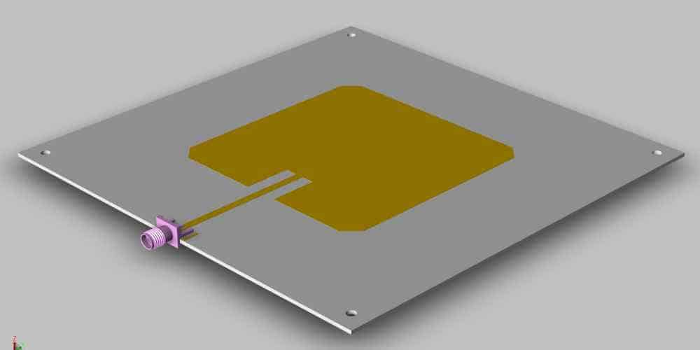
A PCB (Printed Circuit Board) GSM Antenna is a type of antenna that is designed to be integrated into a printed circuit board. It is a compact and cost-effective solution for wireless communication devices that require GSM connectivity.
How Does a PCB GSM Antenna Work?
A PCB GSM Antenna works by transmitting and receiving radio waves. When a signal is transmitted, the antenna converts the electrical signal into an electromagnetic wave that is radiated into the air. When a signal is received, the antenna converts the electromagnetic wave back into an electrical signal that can be processed by the device.
Types of PCB GSM Antennas
There are several types of PCB GSM Antennas available, including:
- Monopole Antennas: These antennas consist of a single element and are easy to integrate into a PCB due to their simple design.
- Dipole Antennas: These antennas consist of two elements and are more efficient than monopole antennas but are also more complex to integrate into a PCB.
- Patch Antennas: These antennas consist of a flat patch of metal and are ideal for use in compact devices due to their low profile.
When choosing a PCB GSM Antenna, it is important to consider factors such as frequency range, gain, and impedance matching to ensure optimal performance.
Overall, PCB GSM Antennas are a reliable and cost-effective solution for wireless communication devices that require GSM connectivity.
Designing a PCB GSM Antenna

Factors to Consider
When designing a PCB GSM antenna, there are several factors that must be taken into consideration. These include the frequency range of the GSM network, the size and shape of the antenna, and the impedance of the antenna. The frequency range of the GSM network is typically between 850-960 MHz and 1710-1900 MHz, so the antenna must be designed to operate within this range. The size and shape of the antenna will affect its performance, and the impedance of the antenna must match the impedance of the transmission line to ensure maximum power transfer.
Design Considerations
There are several design considerations that must be taken into account when designing a PCB GSM antenna. These include the type of antenna, the ground plane, and the feed point. The most common types of antennas used for GSM applications are the monopole and the patch antenna. The ground plane is an important part of the antenna design, as it provides a reference plane for the antenna and affects its radiation pattern. The feed point is where the antenna is connected to the transmission line, and its location can affect the impedance of the antenna.
Testing and Optimization
Once the antenna has been designed, it must be tested and optimized to ensure that it meets the desired performance specifications. This can be done using simulation software or by building a prototype and testing it in a laboratory environment. The performance of the antenna can be optimized by adjusting the size and shape of the antenna, the position of the feed point, and the location of the ground plane.
In conclusion, designing a PCB GSM antenna requires careful consideration of several factors, including the frequency range of the GSM network, the size and shape of the antenna, and the impedance of the antenna. Design considerations include the type of antenna, the ground plane, and the feed point. Finally, the antenna must be tested and optimized to ensure that it meets the desired performance specifications.
Integration of PCB GSM Antenna

When designing a PCB with a GSM module, it is important to integrate the GSM antenna properly. The PCB GSM antenna should be carefully designed and placed to ensure optimal performance and reliable communication. In this section, we will discuss some guidelines for integrating a PCB GSM antenna.
PCB Layout Guidelines
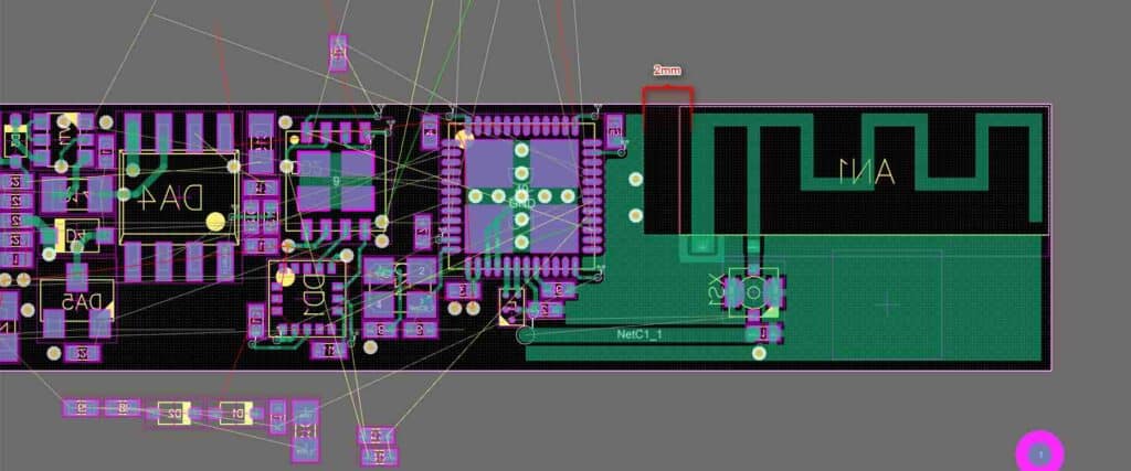
The layout of the PCB is critical to the performance of the GSM antenna. The following guidelines should be followed when designing the PCB layout:
- The GSM antenna should be placed away from other components that may cause interference.
- The antenna should be placed in an area of the PCB with a large ground plane.
- The length of the antenna should be matched to the wavelength of the GSM frequency.
- The antenna should be placed perpendicular to the ground plane.
Integration with Other Components
When integrating the PCB GSM antenna with other components, it is important to consider the following:
- The GSM module should be placed as close as possible to the antenna to minimize losses.
- The antenna should be connected to the GSM module using a short and low-loss coaxial cable.
- The coaxial cable should be shielded to prevent interference.
Testing and Troubleshooting
After integrating the PCB GSM antenna, it is important to test and troubleshoot the system to ensure optimal performance. The following tests should be performed:
- Check the SWR of the antenna to ensure it is within the acceptable range.
- Test the system in different environments to ensure reliable communication.
- Troubleshoot any issues with the system, such as poor signal strength or dropped calls.
In conclusion, integrating a PCB GSM antenna requires careful consideration of the layout, integration with other components, and testing and troubleshooting. By following these guidelines, designers can ensure optimal performance and reliable communication.
PCB GSM Antenna Applications

Mobile Devices
PCB GSM antennas are commonly used in mobile devices such as smartphones, tablets, and laptops. These antennas are compact and can be easily integrated into the device’s PCB, making them a popular choice for mobile device manufacturers. PCB GSM antennas offer high-performance connectivity and can support multiple frequency bands, enabling seamless communication across different networks.
IoT Devices
PCB GSM antennas are also widely used in IoT devices such as smart home devices, wearables, and industrial sensors. These antennas are ideal for IoT devices due to their small size and low power consumption. PCB GSM antennas can operate in harsh environments and offer reliable connectivity, making them a popular choice for IoT device manufacturers.
Automotive Applications
PCB GSM antennas are also used in automotive applications such as GPS tracking, remote monitoring, and infotainment systems. These antennas can be integrated into the vehicle’s PCB and offer high-performance connectivity even in areas with low signal strength. PCB GSM antennas can support multiple frequency bands, enabling seamless communication across different networks.
In conclusion, PCB GSM antennas are widely used in various applications due to their compact size, high-performance connectivity, and reliable operation. With advancements in technology, PCB GSM antennas are becoming more versatile and can support multiple frequency bands, making them a popular choice for manufacturers of mobile devices, IoT devices, and automotive applications.

