Audio amplifier circuit design is a crucial aspect of audio engineering. It involves designing and building circuits that amplify audio signals while maintaining their quality. The design of an audio amplifier circuit is essential to ensure that the audio signal is amplified to the desired level without distortion or noise.
There are various types of audio amplifier circuits, including Class A, Class B, Class AB, and Class D. Each type has its advantages and disadvantages, and the choice of the type of circuit depends on the specific application. The design of an audio amplifier circuit involves selecting the appropriate components, such as transistors, resistors, capacitors, and inductors, and determining their values to achieve the desired performance. The circuit must also be designed to be stable and reliable, with appropriate protection circuits to prevent damage to the amplifier and connected equipment.
Basic Concepts
Amplifier Types
Audio amplifiers are designed to increase the amplitude of an audio signal to drive a speaker or headphones. There are two types of audio amplifiers – analog and digital. Analog amplifiers amplify the signal in a continuous manner, while digital amplifiers convert the signal into digital form and then amplify it.
Amplifier Classes
Amplifiers are classified into different classes based on their operating characteristics. The most commonly used amplifier classes in audio applications are Class A, Class AB, and Class D.
- Class A amplifiers are the simplest type of amplifier and have the highest quality of sound reproduction. They are also the least efficient, as they consume a lot of power even when there is no audio signal.
- Class AB amplifiers are a compromise between Class A and Class B amplifiers. They are more efficient than Class A amplifiers and have less distortion than Class B amplifiers.
- Class D amplifiers are the most efficient type of amplifier and are commonly used in portable devices due to their small size and low power consumption. However, they have higher distortion than Class A and Class AB amplifiers.
It is important to choose the right type of amplifier for your audio application based on factors such as power consumption, distortion, and sound quality.
Design Considerations
When designing an audio amplifier circuit, there are several factors that must be taken into consideration to ensure optimal performance. The following sub-sections highlight some of the most important design considerations.
Gain and Feedback
The gain of an audio amplifier circuit is a crucial factor in determining the overall performance of the circuit. The gain is defined as the ratio of the output voltage to the input voltage. In order to achieve the desired gain, it is important to carefully select the values of the resistors and capacitors used in the circuit.
Feedback is another important consideration when designing an audio amplifier circuit. Feedback is used to reduce distortion and improve stability by feeding back a portion of the output signal to the input of the amplifier. The type of feedback used can have a significant impact on the overall performance of the circuit.
Load Impedance
Load impedance is another important consideration when designing an audio amplifier circuit. The load impedance is the impedance of the speaker or headphones that the amplifier is driving. It is important to match the load impedance to the output impedance of the amplifier to ensure maximum power transfer and minimal distortion.
Noise and Distortion
Noise and distortion are two major concerns when designing an audio amplifier circuit. Noise can be introduced by a variety of factors, including the power supply, the amplifier circuitry, and external sources. Distortion can be caused by a wide range of factors, including nonlinearities in the amplifier circuitry, clipping, and other forms of signal degradation.
To minimize noise and distortion, it is important to carefully select the components used in the circuit and to ensure that they are properly matched and configured. Additionally, it is important to use high-quality components and to shield the circuitry from external sources of interference.
Overall, designing an audio amplifier circuit requires careful consideration of a wide range of factors, including gain, feedback, load impedance, noise, and distortion. By taking these factors into account and carefully selecting and configuring the components used in the circuit, it is possible to achieve optimal performance and high-quality sound reproduction.
Circuit Topologies

There are two main types of audio amplifier circuit topologies: single-ended and push-pull. Each topology has its own advantages and disadvantages, and the choice between them depends on the specific requirements of the application.
Single-Ended Topologies
Single-ended topologies are the simplest type of audio amplifier circuit. They use a single active device, such as a transistor or vacuum tube, to amplify the audio signal. Single-ended topologies are typically used in low-power applications, such as headphone amplifiers or small speakers.
One advantage of single-ended topologies is their simplicity. They require fewer components and are easier to design and build than push-pull topologies. However, single-ended topologies have some drawbacks. They are less efficient than push-pull topologies, and they are more susceptible to distortion.
Push-Pull Topologies
Push-pull topologies use two active devices, one for the positive half of the audio signal and one for the negative half. The two devices are connected in a “push-pull” configuration, where one device pushes the signal while the other pulls it. Push-pull topologies are typically used in high-power applications, such as power amplifiers for large speakers.
One advantage of push-pull topologies is their efficiency. They are able to deliver more power to the load than single-ended topologies, and they are less susceptible to distortion. However, push-pull topologies are more complex than single-ended topologies, and they require more components.
In conclusion, the choice between single-ended and push-pull topologies depends on the specific requirements of the application. Single-ended topologies are simple and easy to design, but they are less efficient and more susceptible to distortion. Push-pull topologies are more complex, but they are more efficient and less susceptible to distortion.
Power Supply
Linear Power Supply
A linear power supply is a simple and reliable solution for powering audio amplifier circuits. It uses a transformer to step down the AC voltage from the mains to a lower AC voltage, which is then rectified and filtered to produce a DC voltage. The DC voltage is regulated using a linear voltage regulator, such as the LM317, to provide a stable output voltage.
Linear power supplies have several advantages over switching power supplies, including low noise and ripple, good transient response, and low EMI/RFI emissions. However, they are less efficient than switching power supplies and can be bulky and heavy due to the transformer and heat sink required for the regulator.
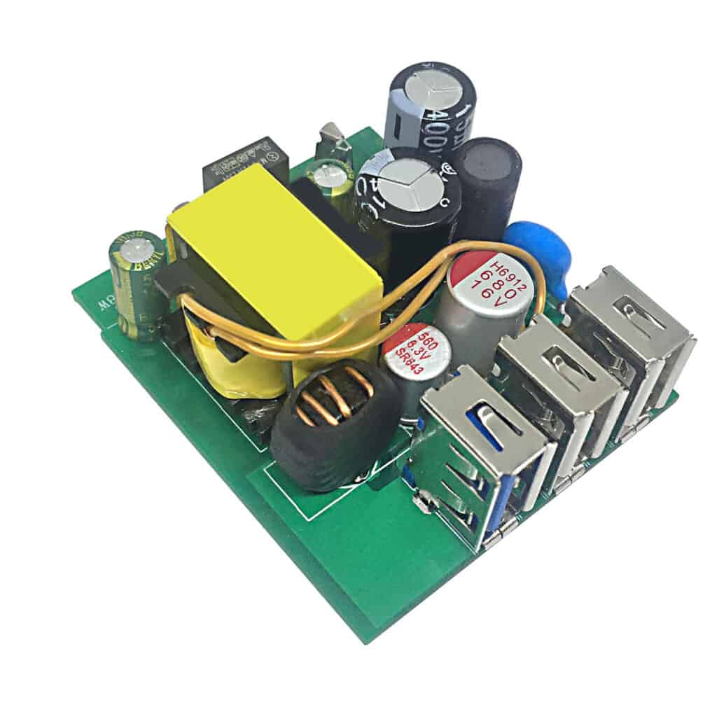
Switching Power Supply
A switching power supply is a more complex solution for powering audio amplifier circuits. It uses a high-frequency oscillator to convert the AC voltage from the mains to a high-frequency AC voltage, which is then rectified and filtered to produce a DC voltage. The DC voltage is regulated using a switching regulator, such as the LM2675, to provide a stable output voltage.
Switching power supplies have several advantages over linear power supplies, including high efficiency, small size and weight, and lower cost. However, they can generate more noise and ripple than linear power supplies, have poorer transient response, and can generate more EMI/RFI emissions.
When choosing a power supply for an audio amplifier circuit, it is important to consider the requirements of the circuit, such as the voltage and current requirements, as well as the desired performance characteristics, such as noise and ripple. Both linear and switching power supplies can be suitable for audio amplifier circuits, depending on the specific requirements and constraints of the application.
Component Selection
When designing an audio amplifier circuit, selecting the right components is crucial to achieve the desired performance. In this section, we will discuss the selection of three essential components: transistors, capacitors, and resistors.
Transistors
Transistors are the key components in an audio amplifier circuit that amplify the input signal. The selection of transistors should be based on their gain, frequency response, and power handling capacity. Here are some factors to consider when selecting transistors:
- Gain: The gain of the transistor should match the required amplification of the circuit.
- Frequency response: The frequency response of the transistor should be wide enough to cover the entire audio spectrum.
- Power handling capacity: The power handling capacity of the transistor should be high enough to handle the maximum power output of the circuit.
Capacitors
Capacitors are used in audio amplifier circuits for coupling, filtering, and bypassing. The selection of capacitors should be based on their capacitance, voltage rating, and tolerance. Here are some factors to consider when selecting capacitors:
- Capacitance: The capacitance of the capacitor should match the required coupling or filtering frequency of the circuit.
- Voltage rating: The voltage rating of the capacitor should be higher than the maximum voltage in the circuit.
- Tolerance: The tolerance of the capacitor should be tight enough to ensure consistent performance.
Resistors
Resistors are used in audio amplifier circuits for biasing, feedback, and load. The selection of resistors should be based on their resistance value, power rating, and tolerance. Here are some factors to consider when selecting resistors:
- Resistance value: The resistance value of the resistor should match the required biasing or feedback level of the circuit.
- Power rating: The power rating of the resistor should be higher than the maximum power in the circuit.
- Tolerance: The tolerance of the resistor should be tight enough to ensure consistent performance.
In conclusion, selecting the right components is crucial to achieve the desired performance of an audio amplifier circuit. When selecting transistors, capacitors, and resistors, consider their gain, frequency response, power handling capacity, capacitance, voltage rating, resistance value, power rating, and tolerance.
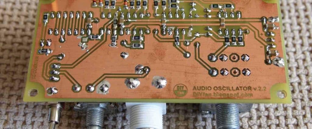
PCB Layout

The PCB layout is a crucial aspect of audio amplifier circuit design. The layout should be optimized to minimize noise, crosstalk, and distortion. Here are some tips to achieve a good PCB layout:
-
Keep the signal path as short and direct as possible. Avoid long traces, loops, and vias, which can introduce parasitic capacitance, inductance, and resistance. Use a ground plane or a star ground topology to reduce ground noise and ground loops.
-
Separate the analog and digital sections of the circuit. Use different ground planes or partitions for each section, and connect them at a single point with a low-impedance path. This will prevent digital noise from affecting the analog signals.
-
Place the components in a logical and compact way. Use a schematic-driven layout to ensure that the physical connections match the logical connections. Group related components together, such as the power supply, the input stage, the gain stage, and the output stage.
-
Use decoupling capacitors and ferrite beads to filter out high-frequency noise from the power supply and the signal lines. Place the capacitors as close as possible to the ICs or the components they are decoupling. Use multiple capacitors of different values and types for better filtering.
-
Test the PCB layout with a prototype before mass production. Use an oscilloscope, a spectrum analyzer, and a distortion analyzer to measure the performance of the amplifier. Check the frequency response, the noise level, the distortion level, and the stability of the amplifier. Make any necessary adjustments to the layout or the component values.
By following these guidelines, you can create a reliable and high-performance audio amplifier circuit with a good PCB layout.
Testing and Troubleshooting
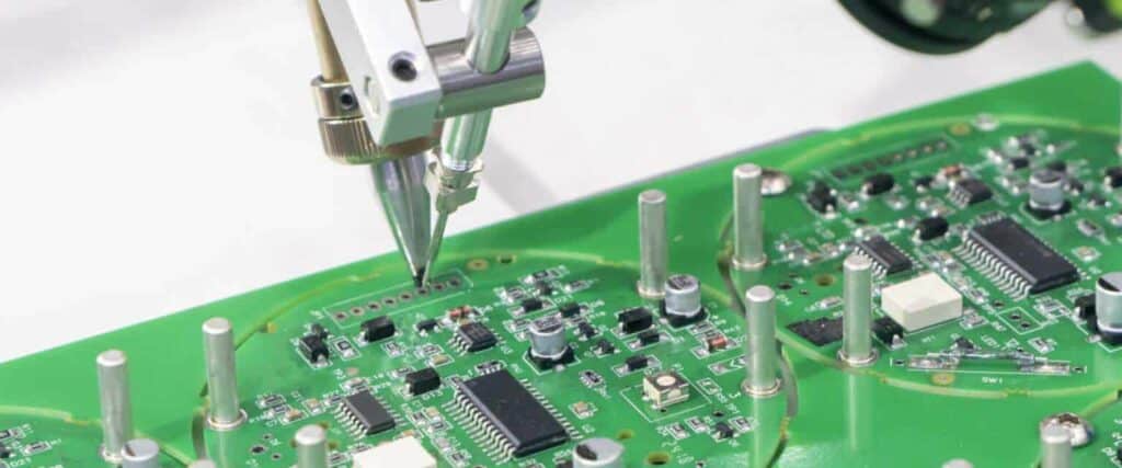
After designing and building an audio amplifier circuit, it is important to test and troubleshoot it to ensure that it is functioning properly. Here are some steps to follow:
-
Start by checking the power supply voltage. Use a multimeter to measure the voltage at the input of the amplifier circuit. If the voltage is too low or too high, the circuit may not work properly. Adjust the voltage as necessary.
-
Check the wiring and connections. Make sure that all the wires and connections are properly soldered and secured. Loose connections can cause unwanted noise and distortion.
-
Test the amplifier with a signal generator and an oscilloscope. Connect the signal generator to the input of the amplifier and the oscilloscope to the output. Adjust the signal generator to produce a sine wave at a frequency within the range of the amplifier. Use the oscilloscope to check the waveform at the output. The waveform should be a clean, undistorted sine wave.
-
Check the biasing of the transistors or tubes. Improper biasing can cause distortion and other problems. Use a multimeter to measure the voltage across the biasing resistors. Adjust the biasing as necessary.
-
Check the feedback loop. If the feedback loop is not properly designed or implemented, it can cause instability and oscillation. Use an oscilloscope to check the waveform at the input and output of the amplifier. Adjust the feedback loop as necessary.
-
If the amplifier still does not work properly, check the components. Use a multimeter to measure the resistance and capacitance of the components. Replace any faulty components.
By following these steps, you can ensure that your audio amplifier circuit is working properly and producing high-quality sound.
