Since amplifier circuit boards are such a crucial element of the design of many electronic devices, having the necessary knowledge of how an audio board is designed is necessary. Such a board is sometimes called the “soul” of an amplifier. Amplifiers play a crucial role in the audio-playback chain. That means that every electronic equipment that makes noise is likely to have an amplifier-printed circuit board installed.
A printed circuit board (PCB) amplifier, for instance, might be used in a loudspeaker or similar device. Therefore, the circuit board of the power amplifier will be the focus of this article.
What is an Amplifier Printed Circuit Board?
You may think of it as a sound amplifier. By connecting to output terminals, a printed circuit board (PCB) may amplify and/or modify an input signal. This integrated circuit board serves as the amplifier’s base. There are different accessories that make up an amplifier PCB.
An electrical component that can receive a signal is a common feature of this kind of printed circuit board. Incorporating a transistor or vacuum tube into the signal path, these components may also improve the audio power amplifier.
Printed circuit boards (PCBs) may be found in many shapes, sizes, and functionality levels. Conversely, the components are wired straight to the base. In a power amplifier, the substrate is the single most important part of the board. A resin and fiberglass substrate serves as a base for the parts.
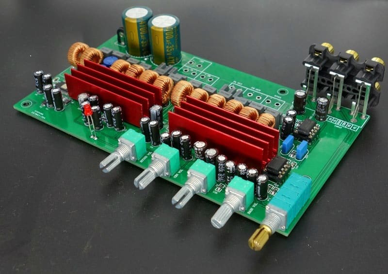
There are several sorts of electronic components on an amplifier board. A single component makes up the amplifier class itself. There are also several capacitors and resistors on the amplifier board, each of which has a specific function. It will also have connectors for input and output, so you can connect your existing equipment and use the amplified signal.
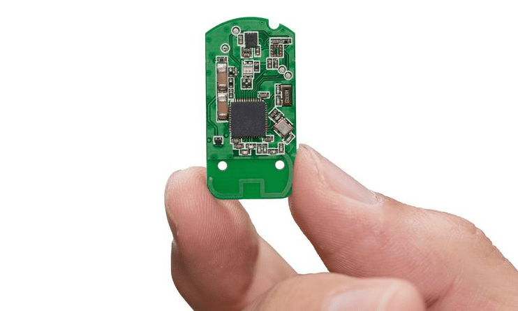
Many modern amplifier chips have large heat sinks linked directly to the circuit board, which helps to keep the chip at an optimal operating temperature. There’s considerable leeway in terms of the size of the amplifier board. That depends on the particulars. Amplifiers for many pairs of headphones that are both portable and lightweight.
The completed amplifier board must take up no more than a few square inches of space. A professional audio amplifier’s printed circuit board (PCB) or a large audiophile home amplifier’s PCB might be sizable and power-hungry. This PCB might be larger than 100 square inches in size.
In most cases, an amplifier board will just be lacking the power supply and a portable amplifier’s battery will be needed to supply power. There is also no need for any additional electronics. Many small amplifiers depend on an external power source. The amplifier boards that power amplifiers may be broken down into two main types, which are power and sound amplifiers.
Audio Circuit Boards Design Tips

Designing audio PCBs is challenging, and some are typically considered moderately professional. To provide a fantastic noise-free layout, even the best designers usually need to put together more than a circuit board. Here are some tips we learned from our interactions:
OpAmp Circuits
Sound quality is negatively affected by fast OpAmps. The LMV722 is a 10MHz OpAmp, however, it wobbles quite a bit when used with automated pots that add a little amount of propagation delay to the criticism resistor, among other issues. Changing to an LMV358, a 1MHz OpAmp will solve the issue.
To create even the most basic circuit, op amplifier boards need to modify an audio signal. It’s all good. The only issue arises if you change certain signals and not others since this would result in an unnatural sound.
Capacitors
You may use them everywhere you need to visually distinguish one element from another. It’s adequate with 100nF, although 100nF is the absolute minimum you should use, 220nF is an excellent starting point if you’re short on cash or storage.
In general, capacitors made of ceramic or clay should be avoided. The logic behind this is that a piezoelectric impact on an AC signal may be generated when a capacitor burns out. Use a polymer, preferably polypropylene although any poly will do. It’s great for ultra-clean uses, but not a mainstream audio industry standard.
Use tantalum capacitors with caution when dealing with audio signals (some originators may differ; however, they can cause severe issues). PPS is a common substitute for polycarbonate (Polyphenylene Sulfide).
Interfacing
When connecting with other pieces of hardware, such as when running different PCBs that include sound hardware assurance, the GND associates that connect the two boards should preferably be at the place where the sound simple sign association point is located.
In any scenario, it is strongly suggested that a resistor with a rating of 100R be inserted between any GND circuits and the GND. This step will prevent the production of ground circles by preventing the formation of ground circles.
Signal
If it is at all feasible, you should try to avoid transferring audio signals to and from ICs that are working in parallel on the PCB. Doing so may cause movements that feed on output to input. Bear in mind that even 5 mV has the potential to produce a significant amount of noise.
Maintain a separation between the digital ground planes, the sound GND, and sound hardware in general. Simply positioning tracks in too close a proximity to airplanes in flight might cause noise to be introduced into the sound.
Grounding
The framework’s ability to unlock the device’s full potential relies heavily on its grounding. Extreme RF sensitivity, crosstalk, interference, and distortion are all possible outcomes of a weakly grounded framework. While the time spent on framework grounding is up for discussion, a volume of potential problems may be avoided by following a well-thought-out approach.
Each framework’s foundation was designed to perform two essential tasks. In the simplest terms, it is the route taken by all outgoing flows from a device. Second, it is used in both digital and analog circuits as a reference voltage. If the ground voltage was uniform everywhere, grounding would be a straightforward process.
All wires and cables experience some degree of interference. The voltage will decrease proportionally whenever the current is passing through the ground. Any closed loop of wire may function as a frame for an inductor.
It indicates that the current path has some inductance everywhere current flows from the battery to a heap and back to the battery. At high frequencies, the inductance contributes to the ground impedance.
