PCB soldering refers to the soldering electrical circuitry boards process. This sort of soldering is a type of the most fundamental methods that anybody desiring to deal with gadgets and electrical circuitries must learn. While there are a wide range of ways you can finish the soldering procedure, the most essential clarification of the soldering procedure is that it’s a method of combining two little pieces on the outside of the PCB. At the end of the day, soldering is a method of interfacing at least two diverse electrical parts on your circuitry board. At the center of the soldering procedure, the activity itself is very basic. All you have to finish the easiest soldering activity is a solder iron, some solders and the parts that you are soldering together. A solder iron looks somewhat like a pen and is an instrument that gets incredibly hot, dissolving the patch and utilizing it to consolidate your two pieces. While there are various sorts of solders, it is typically a metal amalgam of lead or tin joined with silver or brass, intended to have a low liquefying point. As the solder iron melts this metal, it is then utilized somewhat like paste to adhere to sorts out. As the solder metal becomes cooler, it will re-solidify into one huge shape that associates the two sections.
Different Soldering Methods. There are a few different methods to solder an electronic board, which to a great extent separate into two separate procedures known as hard and soft soldering. How about we take a gander at these two distinct strategies now.
1. Hard PCB Soldering
If we talk about hard soldering then it is a procedure that utilizes a rigid solder to combine/join two diverse metal components together by spreading all through the openings of the segments that become opened as they’re presented to high temperatures. As a procedure, hard soldering is comprised of two littler sub-forms known as silver and brazing soldering. As the name recommends, the silver one uses a silver compound, regularly cadmium-silver, as a spacefilling metal. This strategy is utilized to manufacture little parts and furthermore complete specific sorts of support on a circuit board. The silver is utilized for this procedure since it offers a free-running singularity, in spite of the fact that it isn’t normally a perfect decision for space filling all alone. This is the reason another flux is typically used to make dependable silver soldering. Then the brazing soldering is a method used to associate two terminals made of base metals by utilizing fluid filler metal. The outcome is a solid joint that associates the two distinct terminals. For brazing, the brass is commonly utilized as the filler specialist.
2. Soft PCB Soldering
Next is about soft soldering. It is a procedure utilized for appending little segments onto the bigger PCB. These little segments will as a rule have a low-condensing temperature that will start to separate under the high temperatures of the warmth source. Instead of just liquefying the part, be that as it may, an extra advance must be utilized to append the segment to the board. For this situation, this additional progression is a filler metal, which is regularly a tin-lead amalgam. The most significant component of this amalgam is that its dissolving temperature must be more prominent than 752°F. The utilization of this amalgam is vital during the soldering procedure, since it goes about as a coupling specialist between the part and the board, holding the two together firmly. Commonly, a gas light will be utilized to make the essential warmth for this venture, making the amalgam separate and tie the segment to the board.
Soldering Equipments that We Need
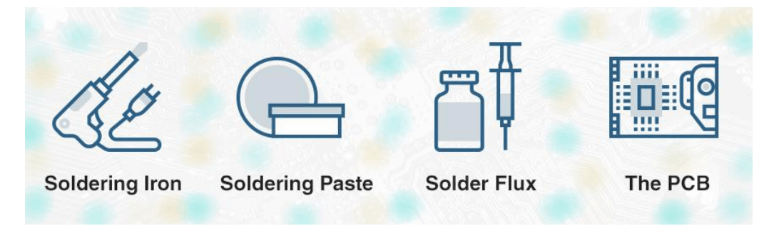
Figure 1 Essential things for PCB soldering
The best equipment for soldering gadgets and the particular devices you will requirement for a binding venture will fluctuate contingent upon the exact idea of your arrangements. A fundamental rundown of the basics that you will likely need, regardless of what you are soldering, in any case,
will include:
1. The PCB
The PCB is your board which is based on your desired circuitry design. All the process of soldering you will do, will happen on the outside of this board as you utilize your patching apparatuses to associate different parts and terminals to each other and to the board.
2. Solder Flux
This material is a refining agent. With regards to soldering, this flux fills three distinct needs at the same time, making it a fundamental device to have close by for any venture. To begin with, it sanitizes the parts you are soldering . It likewise finishes off any additional air that may come into contact with the material, along these lines forestalling future rust. At last, it improves the trickling singularity of the solder itself.
3. Soldering Paste
This solder paste will seem as though a dim clay like material. You’ll utilize this past to combine the different leads of chip bundles to association closes on a PCB.
4. Soldering Iron
If we talk about soldering iron then it is a handheld instrument that gives the warmth source expected to soften the solder. These instruments are commonly pencil-like fit as a fiddle and comprise of a few distinct parts that cooperate to shape an agreeable, commonsense and simple to-utilize apparatus. While most irons are genuinely little, they’re likewise accessible as bigger solder guns. Regardless of their shape or size, all of soldering irons will have a similar fundamental parts. These parts are:
– Rest: While not part of the iron itself, the rest is a fundamental frill that gives you a spot to put the iron aside to free your hands. This rest forestalls your table, counter or workspace from being harmed by the warmed iron in the event that you should lay the iron straightforwardly on this surface.
– Solder wick: Your iron tip is lead of the pencil, at that point think about wick of the solder as an eraser. The wick is created from copper wire, meshing together and utilized for expelling additional solder that won’t be required.
– Wand: This is the solder iron handle and the segment that you will clutch. The wand normally includes a cushioned grasp that gives you something to hold serenely and protects you from the warmth of the iron.
– Tip: Think of this as the lead at the tip of the pencil, and the piece of the iron that will be contacting the solder. This is the piece of the instrument that warms up and that you’ll use to soften and control the solder.

Temperature of PCB soldering. Good solder irons completed by temperature control are essential. Ensure if the solder iron you choose has effectively replaceable tips. In case you are new to this process, a silicone of heatproof link is suggested, so it will not liquefy on the off chance that it contacts the high temperature iron. Likewise, you’ll need to consider a stand for soldering, a sodden wipe to vanish the tip of iron, and solder. Patch plait will wick overabundance weld away if there’s a slip-up, and for “enormous solder spills,” there’s a hand device named a desoldering pump with vacuum ability or people call it “solder sucker” which forces of pull abundance weld away. Tenderfoots to soldering process may likewise need to utilize a warmth sink instrument, as warmth brought about by the procedure of soldering can harm a few parts. Heat-sinks lighten a portion of the problems brought about by overabundance heat, keeping the temp. from expanding a lot on segments, for example, reed switches,
semiconductors, and coordinated chips (ICs). Indeed, even a straightforward crocodile cut is desirable, since this is simple on the pocket and scatters heat hence you can enable heat longer since you will solder and prevent from harming your parts. To utilize the clasp, append this to
its lead that is in the middle of body of the components and the proposed solder joint.
Tips to Enhance Endurance of Soldering Tip and Diminish Cost. Be that as it may, there are approaches to enhance tip endurance and diminish expense. Some key focuses to recall when soldering incorporate the accompanying:
1. If utilizing a wipe, don’t oversoak it. Recollect that everytime the tip contacts the wipe, a warm stun happens, conceivably harming the plating.
2. When not utilizing iron of the soldering, turn-off the power. Embellishments, for example, “shut down” capacities will absolutely help tip endurance however killing the force flexibly when not being used will help significantly more.
3. Ensure to tin the tip with solder consistently. Solder secures plating of the iron and forestall oxidization. A consumed or darkened tip won’t take the solder.
4. Don’t use pincers to expel the tip. Excessive weight can without much of a stretch misshape tips. Utilize the tip expulsion cushion.
SMT Soldering
SMT with the related SMDs, empower PCB get together of electronic hardware to be definitely more productive than having not-new leaded innovation been utilized. At the point when this was presented, SMT reformed PCB get together, making it a lot of times quicker, and the completed outcomes more solid. Anyway to match with PCB get together strategies for soldering which empower volume PCB get together and producing should be utilized. The soldering procedures needed for SMDs among the PCB manufacture requires to guarantee the parts are held set up among soldering, the parts are not harmed, and the last patched quality is really good. One of fundamental driver of hardware disappointment in past time has been nature of soldering, and also by guaranteeing quality of the soldering is exceptionally good, the PCB gathering procedure can
be improved and the general gear unwavering quality and quality can fulfill the most elevated guidelines.
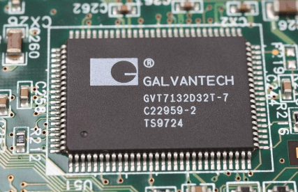
Figure 2 SMT components on PCB
Basis for particular SMT soldering procedures. In spite of the fact that in the absolute first long stretches of utilizing SMT, soldering in the past time was here and there accomplished physically, this isn’t practical in most by far of real cases right now for 2 reasons:
– The amounts of circuits typically delivered couldn’t be accomplished utilizing manual techniques.
– The really small size of parts and the tracks is excessively little for manual tasks and customary soldering.
Clearly some soldering with manual technique is needed for exercises like fix, adjustment and modify.
Process of SMT soldering. There are a few phases needed to patch SMDs to the boards. Anyway there are 2 fundamental techniques for soldering which are utilized. These two procedures need boards to be spread out with somewhat extraordinary PCB configuration rules, and also they additionally need SMT soldering procedure to appear as something else. The two primary strategies to solder SMT parts are:
1. Reflow soldering: This is by a long shot the favored strategy nowadays. Inside the PCB collecting, board of the circuitry has solder implemented via solder screen. Segments are then positioned onto board and applied set up by paste of the solder. Indeed, even before board
soldering this is adequate to keep the parts set up gave the board isn’t shocked or thumped. Then the circuitry board pass-trough an infrared radiator and the patch is mellowed to give incredible joint to conductivity of the electrical and mechanical quality.
2. Wave soldering: A procedure for soldering parts that was initially one of ones presented. It involves having a little shower of liquid solder that is streaming out affecting a little wave. The sheets with their parts are disregarded the particular wave and wave of the solder gives the parts from solder to the another solder. For this procedure, parts should be hung on place, frequently by a little speck of paste so they don’t move among the solder procedure. The soldering procedure is a basic component of the general PCB collecting process. Regularly board quality is observed at every stage and also the outcomes took care of back to keep up and streamline the procedure for the best yield. Likewise the soldering procedures needed for hardware are sharpened to address the SMDs issues and the procedures utilized.
Through-Hole Soldering
Is Through-Hole Soldering is Still Important in the Modern Electronics? Odds are, there’s not as a very remarkable hint of through-opening parts in most purchaser gadgets since there is already generally. With the presentation of SMT parts, through-gap segments appeared on a way to
outdated nature alongside the specialty of through opening welding. Through-opening parts despite everything discover their utilization, however. While the interest for littler and financially savvy hardware has seen SMT segments thriving, their through-opening partners keep on serving
at their specific manner. Through-opening segments will in general be more strong, and workable contrasted with SMT parts. Accordingly, through-opening parts can in any case be favored in modern, military, and aviation applications that request unwavering quality in outrageous
conditions.
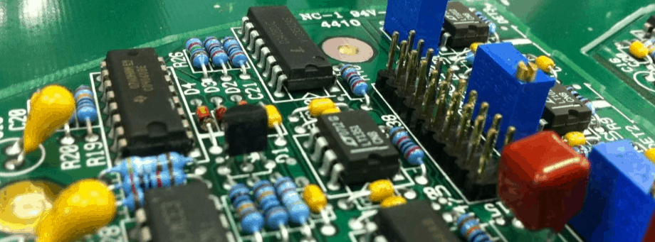
Figure 3 Through-hole components on PCB
Soldering Issues in Through-Hole Components. Through-opening segments are commonly bigger than SMT parts, however that doesn’t imply that welding through-gap segments are a stroll in the recreation center. Contingent upon the aptitudes of individual and also how to plane the PCB, there might be a few obstructions when through-opening patching is focused. It wouldn’t be weird in the event that you made some hard memories setting the through-gap parts onto the impression. Such real cases are a sign which the PCB planner has created the gap on the cushion excessively little. On the opposite finish of boundaries, having excessively enormous of a gap makes a segment free while opening it pass through. Such circumstances occur when the segment you’re dealing with are conventional components in which no direction on the suggested impression measurement.
You may likewise experience issues when fastening pin into the cushion. On the off chance that ring of the annular is excessively tight, you’ll see that the weld experiences issues clutching the cushion. Furthermore, inordinate warming may detach the cushion from PCB base. Yet, that is not
the finish of loathsomeness stories with soldering of through-hole. Pin of the ground is famous for drying or breaking a bind joint. That is on the grounds that the cushion is associated with ground plane, also the warmth disperses rapidly before a safe weld joint is framed. Perhaps the most ideal methods you can defeat any test with through-gap welding and even the desoldering of the throughhole is learning potential entanglements associated with the 2 procedures.
Improving Soldering Process of the Through-Hole Components with PCB Design Optimization. While the facts confirm which machines are considering patching on most parts, some through-gap segments are as yet being physically fastened. This is generally evident when
PCB houses SMT parts on the two layers. In any case, this is still acceptable practice to advance your PCB plan for through-opening welding. For a beginning, guarantee that the annular ring and hole size is satisfactory for pin of the physical to be embedded and fastened. Adhere to the suggested measurement by the part maker.
When implementing ground plane in the top of through-hole segments, recollect to arrangement the arrangement for warm reliefs. Warm reliefs prevent ground plane apart from associating with the cushion in its whole periphery. Rather, it associates with the cushion with 2 or 4 slim copper
follow. This keeps heat from dispersing rapidly and make joint issues. To boost effectiveness, you can attempt to put all SMT parts on a similar side of through-gap segments. Doing so permits the through-gap segments to be soldered as opposed to experiencing the more expensive work patching process. Making impressions for through-opening parts require accuracy and solid PCB structure programming.
SMT vs Through-Hole
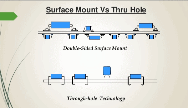
While picking electrical segments for another PCB could be a dull errand, it is evidently significant. Creators need to glance via 10 or even many variations of a section and keep an eye on nowadays stock, future accessibility, and new parts. These choices and contemplations are significant, yet before picking segments, we have to think about a considerably more crucial inquiry: SMT vs through-hole? Numerous individuals see through-gap gadgets as antiquated, with SMT is being cutting edge style. Whilst this might be valid for some applications, through-opening
innovation despite everything offers some huge points of interest in specific conditions. Throughopening segments exceed expectations in sheets which will be dependent upon warm pressure or high mechanical and have superior force necessities. SMT, then again, is more qualified for little,
not-heavy PCBs that will be created at a bigger scope.
The Pros and Cons of using Through-Hole Parts. On the off chance that you disclose an irregular purchaser electronic gadget today, you most likely won’t find numerous through-gap segments inside. This doesn’t mean they don’t have a spot in PCB world any longer; it’s simply that most of today’s circuits don’t require their one of a kind focal points. Through-opening gadgets exceed expectations in genuinely requesting applications that additionally have high warmth or force prerequisites and could be helpful in prototyping. These are, be that as it may, less helpful
on little sheets that should be modestly mass delivered.
With regards to tough warmth and stun necessities, through-gap’s mystery happens in soldering procedure. This technique for connection is substantially more secure comparing to mounting SMT style and permits through-opening sheets to go into more physical, warm pressure. By and large, through-opening parts are additionally bigger comparing to SMT ones, that implies they can typically deal with higher force applications too. Another favorable position of style of throughopening soldering is that segments can be all the more effortlessly evacuated and supplanted during
model emphasess. On the off chance that you have to wipe another variation of some segment, essentially expel it and bind in a substitution.
These favorable circumstances all accompany costs, essentially as far as load up land, fabricating expense, and time of turnaround. SMT parts can be put into a PCB altogether quicker than throughopening gadgets. Sheets with through-gap parts additionally need gaps penetrated via them, and
also both of the prerequisites cause higher board expenses. Through-gap segments are likewise genuinely bigger than SMT gadgets and must be welded aside of board. So on the off chance that you require a small PCB which can be economically made, through-hole parts maybe not for you.
The Advantages and Disadvantages of using SMT Devices. Devices with SMT type are exceptionally little, quicker to put, and could be embedded on a two-sides PCB, causing SMT sheets a lot less expensive to fabricate. The get together procedure doesn’t generally go easily, as
SMT segments can experience the ill effects of an assortment of problems during PCB assembling.
On the off chance that you want a little, not-heavy PCB which is modest to cause, SMT parts are likely the correct decision. They’re fundamentally littler than through-opening gadgets and hence the weight becomes far less. Minuscule parts mean denser arrangement on the PCB, and also with
numerous hardware today concentrating on the size, this bit of leeway can be difficult to be beaten. The physical type of SMT segments likewise fits quicker arrangement during get together, bringing about more affordable operations over an item lifetime.
Regardless of the obvious points of interest, SMT fabricating provides its own arrangement of remarkable difficulties. While parts can be put all the more rapidly, the apparatus needed to do hence is over the top expensive one. Such some high capital ventures for the get together procedure implies that SMT fpga parts could push expenses for a low volume model sheets. Surface mounted segments require more accuracy during assembling because of the expanded multifaceted nature of steering blind/covered vias rather than through-gap. Exactness is likewise significant during structure, as infringement of your agreement producer’s (CM’s) DFM cushion format rules can prompt mounting issues, for example, tombstoning, that can altogether diminish the result ratethrough a creation run.
When Should We Use SMT vs Through-Hole? While SMT is more up to date, more smaller segment bundle style and also through-gap is more qualified for bigger loads up, neither one of the mountings style is disappearing at any point in the near future. Every alternative offers remarkable points of interest. In case you’re structuring a military evaluation PCB or digging into basic framework configuration including requesting physical and warm prerequisites, you will presumably need to continue with through-gap segments. In case you’re making the following
minuscule customer gadgets where each penny matters, at that point SMT gadgets are likely for you.
