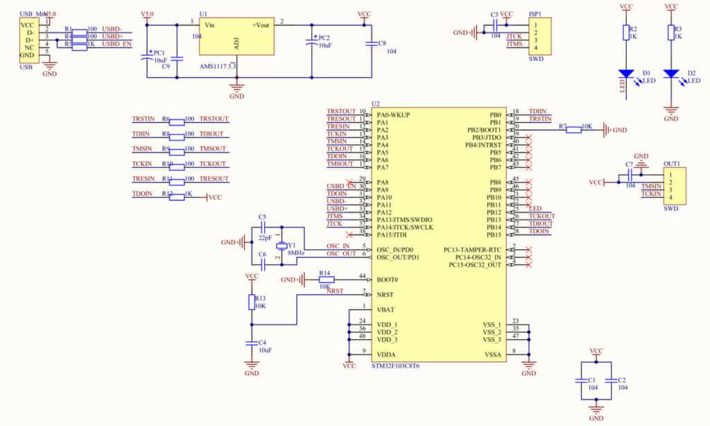
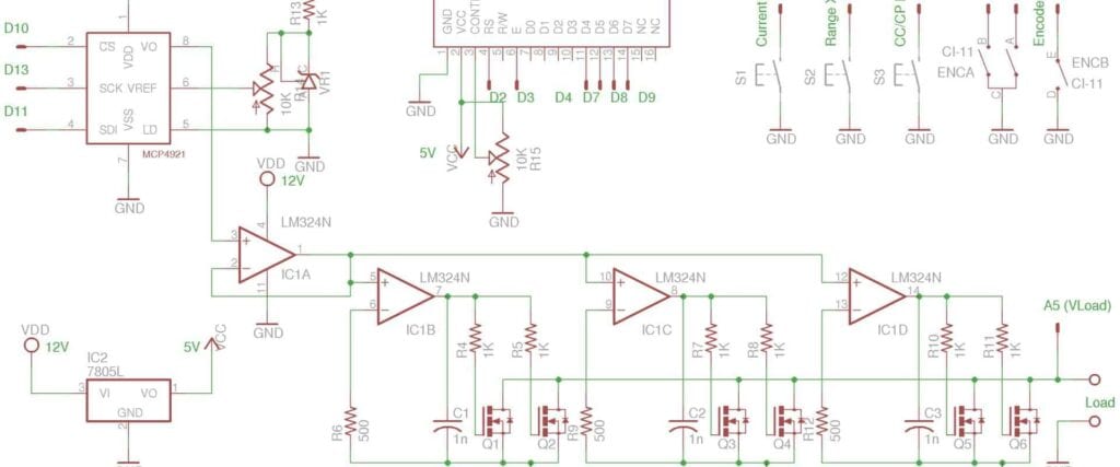
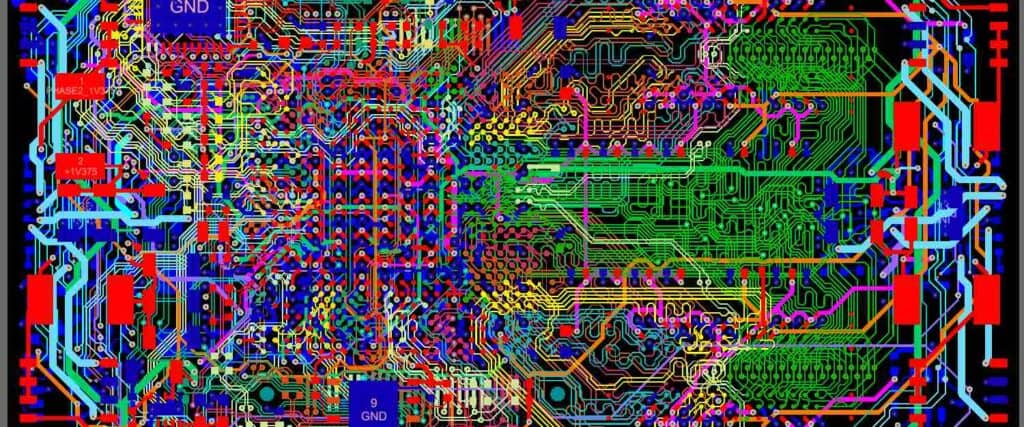
Cadstar Schematic is an advanced software tool used to design and simulate electronic circuits. It is widely used by engineers and designers in industries such as aerospace, automotive, telecommunications, and more. The software offers a range of features that allow users to create complex circuit diagrams quickly and efficiently.
One of the key benefits of Cadstar Schematic is its intuitive user interface. The software is designed to be easy to use, even for those who are new to electronic circuit design. The drag-and-drop interface allows users to quickly add components to their circuit diagrams, while the built-in library of symbols and components makes it easy to find the parts you need. Additionally, the software includes a range of tools for checking and validating your designs, ensuring that your circuits are accurate and error-free.
Overall, Cadstar Schematic is an essential tool for anyone involved in electronic circuit design. Its powerful features and user-friendly interface make it a popular choice for engineers and designers around the world. Whether you are designing circuits for consumer electronics, industrial machinery, or any other application, Cadstar Schematic is an excellent choice for your design needs.

Overview
What is Cadstar Schematic?
Cadstar Schematic is a powerful and user-friendly schematic capture tool that is used by electronic design engineers and PCB designers worldwide. It is a part of the Cadstar suite of PCB design software products developed by Zuken, a leading provider of electronic design automation (EDA) software.
Cadstar Schematic is designed to help users create, edit, and manage complex schematic diagrams quickly and efficiently. It offers a wide range of features and tools for designing schematic diagrams, including hierarchical design, net connectivity checking, and cross-probing between schematic and layout.
Features of Cadstar Schematic
Cadstar Schematic comes with a host of features that make it an indispensable tool for electronic design engineers and PCB designers. Some of the key features of Cadstar Schematic include:
-
Hierarchical design: Cadstar Schematic allows users to create hierarchical designs that can be easily managed and edited. This feature helps users to break down complex designs into smaller, more manageable parts, making the design process faster and more efficient.
-
Net connectivity checking: Cadstar Schematic has a powerful net connectivity checking feature that ensures that all the connections in the schematic diagram are correct and error-free. This feature helps to eliminate errors and reduce the time required for design verification.
-
Cross-probing between schematic and layout: Cadstar Schematic allows users to cross-probe between the schematic and layout views, making it easy to navigate between the two views and locate components and nets.
-
User-friendly interface: Cadstar Schematic has a user-friendly interface that is easy to navigate and use. The software is designed to be intuitive and user-friendly, making it easy for users to get started with the software and start designing schematic diagrams quickly.
In summary, Cadstar Schematic is a powerful and user-friendly schematic capture tool that offers a wide range of features and tools for designing complex schematic diagrams quickly and efficiently. With its hierarchical design, net connectivity checking, cross-probing, and user-friendly interface, Cadstar Schematic is an indispensable tool for electronic design engineers and PCB designers.
Creating a Schematic

Starting a New Schematic
To begin creating a schematic in CADSTAR, you will need to start a new schematic project. This can be done by selecting “File” from the menu bar and then choosing “New” and “Schematic” from the drop-down menu. You will then be prompted to choose a template for your schematic, or you can create a new template from scratch.
Adding Components
Once you have started a new schematic project, you can begin adding components to your schematic. To add a component, simply select “Place Component” from the toolbar or right-click on the schematic and choose “Place Component” from the context menu. You can then choose the component you want to add from the component library and place it on the schematic.
Connecting Components
After you have added components to your schematic, you will need to connect them together. To connect components, select the “Place Net” tool from the toolbar or right-click on the schematic and choose “Place Net” from the context menu. Then, simply click on the pins of the components you want to connect to create a net.
Once you have connected all of your components, you can then annotate your schematic and generate a netlist for use in PCB layout.
Overall, CADSTAR provides a user-friendly interface for creating schematics, and the process of starting a new schematic, adding components, and connecting components is straightforward and intuitive.
Editing a Schematic

Moving Components
When working on a schematic in Cadstar, it is important to be able to move components around as needed. To move a component, simply click and drag it to the desired location. If you need to align components, you can use the grid and snap-to-grid features to ensure precise placement.
Deleting Components
If you need to delete a component from your schematic, simply select it and press the delete key on your keyboard. You can also use the cut or copy and paste functions to move components to a different location.
Labeling Components
Labeling components is an important part of creating an organized and easy-to-read schematic. To label a component, simply right-click on it and select “Properties”. From there, you can enter the desired label in the “Designator” field. You can also add additional information, such as the component’s value or manufacturer, in the “Comment” field.
Overall, Cadstar provides a user-friendly interface for editing schematics. By using the tools and features available, you can easily move, delete, and label components to create a clear and organized schematic for your project.
Design Rule Checking

What is Design Rule Checking?
Design Rule Checking (DRC) is a process that verifies the schematic design against a set of rules defined by the designer. It is an essential step in the design process that ensures the design is free from errors or violations of the design rules. DRC checks for errors such as short circuits, open circuits, and other design rule violations.
How to Run Design Rule Checking
To run Design Rule Checking in Cadstar Schematic, follow these simple steps:
- Open the schematic design you want to check.
- Click on the DRC icon in the toolbar or go to Tools > DRC.
- In the DRC dialog box, select the rules you want to check.
- Click on the Run button to start the DRC process.
- Review the DRC report to identify and correct any errors or violations.
Common Design Rule Checking Errors
Some common errors that may be identified during the DRC process include:
- Short circuits: Two or more nets are connected that should not be connected.
- Open circuits: A net is not connected to another net or a power source.
- Clearance violations: Components or nets are too close to each other, violating the minimum clearance rules.
- Pin swapping: Pins are swapped between components, causing incorrect connections.
To avoid these errors, it is essential to define and follow a set of design rules and run DRC regularly during the design process.
In conclusion, Design Rule Checking is a critical step in the design process that ensures the design is free from errors and violations. By following a set of design rules and running DRC regularly, designers can identify and correct errors early in the design process, saving time and reducing the risk of costly errors later on.
Exporting and Importing

Exporting a Schematic
Exporting a schematic in Cadstar is a simple process. First, open the schematic you want to export. Then, go to the File menu and select “Export”. In the Export dialog box, choose the desired file format and location to save the file. Cadstar supports various file formats, including DXF, DWG, and IDF.
Importing a Schematic
Importing a schematic in Cadstar is also straightforward. To import a schematic, go to the File menu and select “Import”. In the Import dialog box, choose the file format of the schematic you want to import. Cadstar supports various file formats, including DXF, DWG, and IDF. Once you select the desired file, Cadstar will import the schematic into your current project.
Supported File Formats
Cadstar supports various file formats for exporting and importing schematics. The following table lists the supported file formats and their descriptions:
| File Format | Description |
|---|---|
| DXF | AutoCAD Drawing Exchange Format |
| DWG | AutoCAD Drawing |
| IDF | Intermediate Data Format |
| EDIF | Electronic Design Interchange Format |
In conclusion, Cadstar offers a simple and efficient way to export and import schematics. With support for various file formats, users can easily share and collaborate on their designs with other CAD tools.

