High-speed digital circuits are an essential component of modern electronics. These circuits are designed to transmit and process data at extremely high speeds, making them ideal for use in a wide range of applications, from telecommunications and networking to aerospace and defense.
The development of high-speed digital circuits has been driven by the need for faster and more efficient data processing. With the increasing demand for high-speed data transmission, the importance of these circuits has only continued to grow. As a result, engineers and researchers have been working to develop new and innovative ways to design and manufacture high-speed digital circuits that are capable of meeting the demands of modern electronics.
In this article, we will explore the world of high-speed digital circuits, including their design, manufacture, and applications. We will also discuss some of the challenges associated with working with these circuits and the latest developments in this exciting field. Whether you are an electronics enthusiast or a professional engineer, this article will provide you with a comprehensive overview of high-speed digital circuits and their importance in modern electronics.
Basics of High Speed Digital Circuits
Signal Integrity
Signal integrity is the ability of a signal to maintain its quality, accuracy, and reliability as it travels through a circuit. In high-speed digital circuits, signal integrity is crucial because even small variations or distortions in the signal can lead to errors or data loss. Factors that can affect signal integrity include noise, crosstalk, reflections, and impedance mismatches.
To ensure good signal integrity, designers must carefully consider the following:
- Proper grounding and power distribution
- Minimizing noise and crosstalk
- Using appropriate termination techniques
- Choosing the right components and materials
- Routing signals on appropriate layers and with appropriate trace widths and spacing
Transmission Line Effects
Transmission line effects refer to the behavior of signals as they travel along a conductor that has a significant length compared to the wavelength of the signal. In high-speed digital circuits, transmission line effects become important when the signal frequency is in the range of hundreds of megahertz to several gigahertz.
Some common transmission line effects include:
- Reflections: When a signal encounters an impedance mismatch, some of the signal is reflected back towards the source. This can cause signal distortion or ringing.
- Attenuation: As a signal travels along a transmission line, it loses some of its energy due to resistance and dielectric losses.
- Delay: The signal takes some time to travel along the transmission line, which can cause timing issues or skew between different signals.
- Crosstalk: When two or more signals are routed close to each other, they can interfere with each other due to mutual capacitance and inductance.
To mitigate transmission line effects, designers must consider the following:
- Using controlled impedance traces and vias
- Proper termination and matching of transmission lines
- Minimizing the length and number of vias and connectors
- Proper spacing and shielding of signals to reduce crosstalk
Overall, good signal integrity and proper management of transmission line effects are essential for designing high-speed digital circuits that are reliable and accurate.
Design Considerations for High Speed Digital Circuits

Power Integrity
Power integrity is a critical consideration in high speed digital circuits. The power supply must be stable and clean to ensure proper operation of the circuit. Inadequate power integrity can lead to signal integrity issues and other problems.
To ensure proper power integrity, it is important to minimize the impedance of the power distribution network. This can be achieved by using low-ESR capacitors and minimizing the length of power traces. It is also important to place decoupling capacitors close to the power pins of each IC.
Clock Distribution
Clock distribution is another important consideration in high speed digital circuits. The clock signal must be distributed accurately and with minimal skew to ensure proper timing of the circuit.
To achieve accurate clock distribution, it is important to use low-skew clock distribution networks. This can be achieved by using matched-length traces and minimizing the length of clock traces. It is also important to place clock buffers close to the clock source and to use termination techniques to minimize reflections.
EMI/EMC
EMI/EMC is a critical consideration in high speed digital circuits. The circuit must be designed to minimize its emissions and to be immune to external electromagnetic interference.
To minimize emissions, it is important to minimize the loop area of high-speed signals and to use shielding where necessary. To improve immunity, it is important to use differential signaling where possible and to use proper grounding techniques. It is also important to ensure that the circuit meets the relevant EMI/EMC standards.
Testing and Validation of High Speed Digital Circuits
Test Equipment
Testing high-speed digital circuits requires specialized equipment that can accurately measure and analyze signals at high frequencies. Some commonly used test equipment includes:
-
Oscilloscopes: These devices are used to measure voltage signals over time. High-speed digital circuits require oscilloscopes with high bandwidth and sampling rates to accurately capture and analyze the signals.
-
Signal generators: These devices are used to generate test signals that can be used to test the performance of high-speed digital circuits. Signal generators with high frequency and amplitude resolution are necessary for testing high-speed circuits.
-
Logic analyzers: These devices are used to capture and analyze digital signals. Logic analyzers with high-speed capabilities and deep memory are necessary for testing high-speed digital circuits.
Test Procedures
Testing high-speed digital circuits requires careful planning and execution of test procedures. Some common test procedures include:
-
Eye diagram analysis: This test involves plotting a waveform of a digital signal over time to visualize the quality of the signal. The eye diagram should be open and well-defined for the signal to be considered acceptable.
-
Jitter analysis: This test involves measuring the amount of time deviation in a digital signal. High-speed digital circuits require low jitter to ensure reliable operation.
-
Bit error rate (BER) testing: This test involves injecting errors into a digital signal and measuring the number of errors that occur. High-speed digital circuits require low BER to ensure reliable operation.
In conclusion, testing and validation of high-speed digital circuits requires specialized equipment and careful execution of test procedures. Eye diagram analysis, jitter analysis, and BER testing are some common test procedures used to ensure the performance and reliability of high-speed digital circuits.
Advanced Topics in High Speed Digital Circuits
SerDes
SerDes stands for Serializer/Deserializer, a critical component in high-speed communication systems. It converts parallel data into a serial data stream and vice versa. SerDes technology enables high-speed communication between chips and systems, making it possible to achieve data rates of up to 100 Gbps.
SerDes circuits have become increasingly complex, with more advanced equalization techniques and clocking schemes. These techniques improve signal integrity and reduce jitter, enabling reliable data transmission over long distances.
FPGA Design
Field Programmable Gate Arrays (FPGAs) are programmable logic devices that can be configured to perform specific tasks. FPGAs are commonly used in high-speed digital circuits because of their ability to process large amounts of data quickly.
FPGA designers must be familiar with high-speed design techniques and signal integrity principles to avoid issues such as crosstalk, ringing, and reflections. Proper grounding and power distribution are also critical to ensuring reliable FPGA operation.
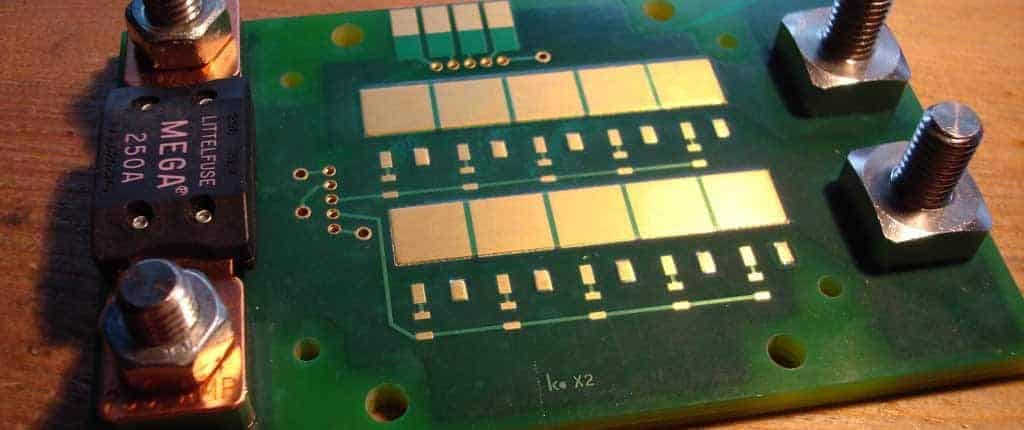
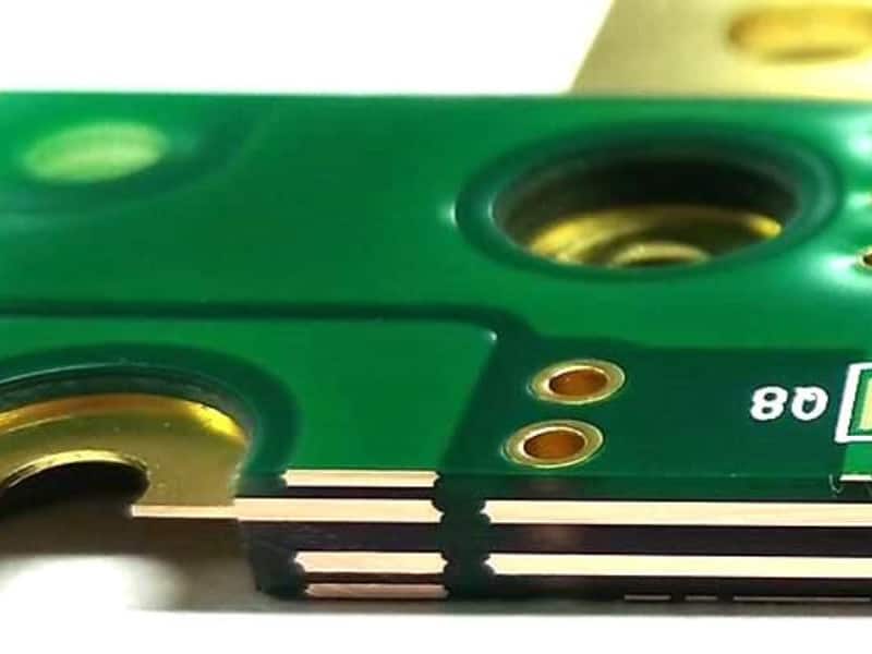
High Speed PCB Layout
High-speed PCB layout requires careful consideration of signal integrity principles, such as controlled impedance, crosstalk, and EMI/EMC. PCB designers must also consider the physical layout of components, trace routing, and layer stackup to ensure proper signal integrity.
Designers often use simulation tools to verify the performance of high-speed PCB layouts before fabrication. These tools can help identify potential issues and optimize the layout for signal integrity.
In conclusion, advanced topics in high-speed digital circuits involve complex technologies and design techniques. SerDes, FPGA design, and high-speed PCB layout are critical components in achieving high-speed data transmission. By following best practices and using simulation tools, designers can ensure reliable and efficient operation of high-speed digital circuits.
