Microelectronics and VLSI design are two fields that have revolutionized the tech industry. Microelectronics involves the study and development of tiny electronic components, such as transistors and diodes, that are used in a wide range of devices, from smartphones to medical equipment. VLSI, or Very Large Scale Integration, is the process of designing and creating integrated circuits that contain thousands or even millions of transistors on a single chip.
The development of microelectronics and VLSI design has led to significant advancements in technology, allowing for smaller, faster, and more powerful devices. The ability to integrate more components onto a single chip has led to the creation of complex systems, such as microprocessors, that can perform a wide range of tasks. These advancements have also led to the creation of new industries and job opportunities in fields such as electronics manufacturing and design.
Overall, the study of microelectronics and VLSI design is critical for those interested in pursuing a career in the tech industry. The ability to design and create complex electronic systems is essential for the development of new technologies and the improvement of existing ones. As technology continues to advance, the importance of microelectronics and VLSI design will only continue to grow.
Overview of Microelectronics
Introduction to Microelectronics
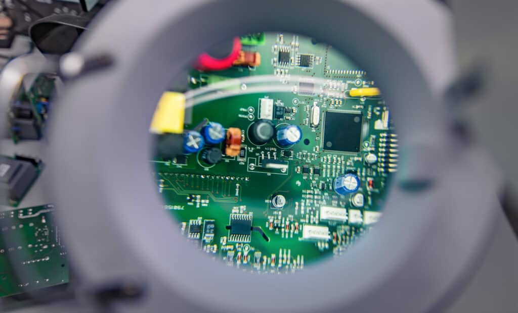
Microelectronics is a branch of electronics that deals with the design and manufacture of small electronic devices and circuits. These devices are typically made from semiconductor materials such as silicon, germanium, and gallium arsenide. Microelectronics has revolutionized the world of electronics by enabling the creation of smaller and more powerful electronic devices.
History of Microelectronics
The history of microelectronics dates back to the early 20th century when the first vacuum tube was invented. However, the real breakthrough came in the late 1940s when the first transistor was invented by William Shockley, John Bardeen, and Walter Brattain at Bell Labs. This invention paved the way for the development of integrated circuits (ICs) in the 1950s, which led to the birth of modern microelectronics.
Applications of Microelectronics
Microelectronics has numerous applications in various fields such as healthcare, communication, transportation, and entertainment. Some of the most common applications of microelectronics include:
-
Smartphones: Microelectronics has enabled the creation of smaller and more powerful smartphones with advanced features such as high-resolution cameras, touchscreens, and GPS.
-
Medical Devices: Microelectronics has revolutionized the healthcare industry by enabling the creation of advanced medical devices such as pacemakers, insulin pumps, and diagnostic equipment.
-
Automotive Industry: Microelectronics has enabled the creation of advanced safety features in automobiles such as airbags, anti-lock braking systems, and traction control systems.
In conclusion, microelectronics has played a significant role in shaping the modern world by enabling the creation of smaller and more powerful electronic devices. Its applications are numerous and diverse, and it is likely to continue to play a crucial role in the development of new technologies in the future.
VLSI Design

Introduction to VLSI Design
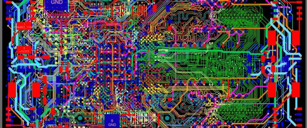
Very Large Scale Integration (VLSI) Design is the process of creating an integrated circuit (IC) by combining thousands of transistors into a single chip. This technology has revolutionized the electronics industry by enabling the creation of smaller, faster, and more powerful electronic devices.
Design Flow in VLSI
The VLSI design flow is a series of steps that are taken to design and manufacture an integrated circuit. The design flow starts with the specification of the circuit, followed by the design of the circuit, verification of the design, and finally the implementation of the design. The design flow is iterative, meaning that the design is refined and improved at each step.
VLSI Design Tools
VLSI design requires the use of specialized software tools that help in the design, simulation, and verification of the circuit. Some of the commonly used VLSI design tools include:
- Electronic Design Automation (EDA) tools: These tools are used for designing and verifying the circuit.
- Simulation tools: These tools are used to simulate the behavior of the circuit to ensure that it meets the design requirements.
- Layout tools: These tools are used to create the physical layout of the circuit.
- Verification tools: These tools are used to verify the correctness of the design.
In conclusion, VLSI design is a complex process that involves the integration of thousands of transistors into a single chip. The design flow is iterative and requires the use of specialized software tools. With the advancement of technology, VLSI design has become an integral part of the electronics industry, enabling the creation of smaller, faster, and more powerful electronic devices.
Digital Design with VLSI
Introduction to Digital Design
Digital design is the process of creating electronic circuits that can process and store digital information. The design of digital circuits is a complex process that involves a combination of mathematical algorithms, logic gates, and other electronic components. VLSI (Very Large-Scale Integration) is a technology that allows for the integration of thousands or even millions of transistors onto a single chip. VLSI technology has revolutionized the field of digital design by enabling the creation of more complex and powerful digital circuits.
Combinational Circuits
Combinational circuits are digital circuits that perform logical operations on two or more input signals to produce a single output signal. These circuits are designed using logic gates such as AND, OR, NOT, NAND, and NOR gates. Combinational circuits are used in a wide range of applications, including digital signal processing, computer arithmetic, and data encryption.
Sequential Circuits
Sequential circuits are digital circuits that use feedback to store and process information. These circuits are designed using flip-flops, which are electronic components that can store a single bit of information. Sequential circuits are used in a wide range of applications, including memory systems, digital clocks, and control systems.
In conclusion, the design of digital circuits with VLSI technology is a complex process that involves a combination of mathematical algorithms, logic gates, and other electronic components. Combinational circuits perform logical operations on input signals to produce a single output signal, while sequential circuits use feedback to store and process information. The use of VLSI technology has revolutionized the field of digital design by enabling the creation of more complex and powerful digital circuits.
Analog Design with VLSI
Introduction to Analog Design
Analog design is the process of designing and implementing analog circuits that process continuous signals. VLSI (Very Large Scale Integration) technology has revolutionized analog design by enabling the integration of complex analog circuits on a single chip. Analog design with VLSI involves designing circuits that operate at high frequencies, consume low power, and occupy minimum area on the chip.
Operational Amplifiers
Operational amplifiers (op-amps) are the fundamental building blocks of analog circuits. They are used to amplify, filter, and process analog signals. Op-amps have high gain, high input impedance, and low output impedance. They are used in various applications such as amplifiers, filters, oscillators, and comparators.
Op-amps can be designed using different topologies such as differential amplifiers, cascode amplifiers, and folded cascode amplifiers. Each topology has its advantages and disadvantages. For example, differential amplifiers have high gain and input impedance but suffer from offset voltage and noise. Cascode amplifiers have high gain and bandwidth but suffer from high power consumption.
Analog Filters
Analog filters are used to remove unwanted frequencies from a signal. They are classified into two types: active filters and passive filters. Active filters use op-amps and other active components to implement the filter function. Passive filters use only passive components such as resistors, capacitors, and inductors.
Analog filters can be designed using different filter topologies such as Butterworth, Chebyshev, and Bessel. Each topology has its advantages and disadvantages. For example, Butterworth filters have a flat response in the passband but suffer from a slow roll-off in the stopband. Chebyshev filters have a sharper roll-off but suffer from ripple in the passband.
In conclusion, analog design with VLSI is a complex and challenging field that requires a deep understanding of analog circuits, VLSI technology, and design methodologies. Analog designers must carefully balance performance, power, and area constraints to achieve optimal circuit performance.
Testing and Verification in VLSI
Introduction to Testing and Verification
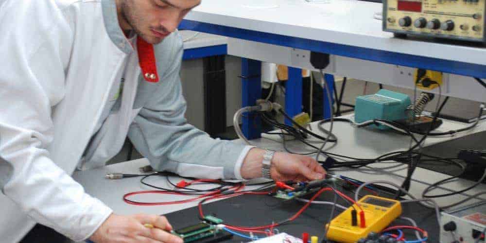
Testing and verification are crucial steps in the VLSI design process. Testing is the process of verifying the functionality of a chip or system, while verification is the process of ensuring that the design meets the specifications and requirements.
The purpose of testing and verification is to identify and correct errors or defects in the design before it goes into production. This helps to reduce the cost of manufacturing and improve the quality of the final product.
Testing Techniques
There are several testing techniques used in VLSI design, including:
-
Functional testing: This technique involves testing the chip or system to ensure that it performs the desired functions.
-
Structural testing: This technique involves testing the chip or system to ensure that it meets the design specifications.
-
Boundary scan testing: This technique involves testing the interconnects between the chips on a board.
-
Built-in self-test (BIST): This technique involves adding test circuitry to the chip or system to test its own functionality.
Verification Techniques
There are several verification techniques used in VLSI design, including:
-
Simulation: This technique involves simulating the behavior of the chip or system under different conditions to ensure that it meets the design specifications.
-
Formal verification: This technique involves using mathematical algorithms to verify that the design meets the specifications.
-
Emulation: This technique involves using specialized hardware to emulate the behavior of the chip or system.
-
Prototyping: This technique involves building a physical prototype of the chip or system to test its functionality.
In conclusion, testing and verification are critical steps in the VLSI design process. By using these techniques, designers can ensure that the final product meets the design specifications and is free of defects.
