Printed Circuit Boards (PCBs) are originally designed to bolster the performance of different kinds of electronics. However, the capabilities can further be extended if pressure sensors were used.
Modern PCBs can work with pressure sensors. In this article, we discuss the role of the PCB pressure sensor.
What is a Pressure Sensor?
Let us start by understanding how the sensor works. By default, the function of a pressure sensor is to detect the following: turbulences, dynamic pressure fluctuations and pulsations. These detections are usually made in the high-static pressure environments.
Going by this, if your PCB needs require extended pressure usage, it may be a good idea to use this type of pressure sensor. Little wonder why the sensor has become an integral part of circuit boards used for high-end applications, such as automotive electronics.
How Does the Sensor Impact PCB’s Performance?
Now that we are clear about how the sensor works on a standalone, let us talk about the relevance to Printed Circuit Boards (PCBs).
The primary function of the sensor to the circuit board is to work as a transmitter that converts the (excess) pressure into an analog electrical signal.
You can also be sure that the sensor will help balance the circuit board’s performance, in terms of measuring the small pressure fluctuations at high-static pressure environments/levels.
The Measurement Principles
One of the major considerations to optimizing and making the most out of the PCB pressure sensor is to take note of the different principles and methods of measuring its performance.
The two common ways are through piezoresistive and capacitive effects. The former (the piezoresistive effects) are the most popular. It is also what we will discuss fully in this article.
What is the Piezoresistive Effect?
The primary role of the piezoresistive effect is to measure the dynamic change in the circuit board’s temperature. Nevertheless, it is not a better option for other use cases, especially when you consider that it is not always used with static pressure that are sensitive-inclined.
Using Piezoresistive Transducers
Going by the overall functions of the piezoresistive effect, the same can be leveraged to make something relevant out of the circuit board. It is for this purpose that it is designed as a piezoresistive transducer – a device dedicated to the (seamless) conversion or optimization of one energy form to another.
The PCB pressure sensor takes the form of the piezoresistive transducers to facilitate the conversion of some of the electrical charges produced by some solid material forms. These charges are converted into the required energy.
The Types of PCB Pressure Sensors

Realizing the importance of these sensors, one thing you must do is to find out how it compares with the options out there.
One of the major things to do is to take note of the different types of PCB pressure sensors. The selection of any of the options depends on what you want to use it for.
Below are some of the common types and how they work:
- Mountable PCB Pressure Sensors: as the name signifies, these sensors are best used with Printed Circuit Boards (PCBs) that have a majority of the components mounted or placed with the use of the Surface Mount Technology (SMT).
- Hazardous Area Pressure Sensors: these are the dedicated or specific pressure sensors sued with the PCB areas/locations that have more hazardous components or which are more susceptible to hazards.
- Combined Pressure and Temperature Transducers: these are the PCB pressure sensors that are ideally used with the applications or devices that require more space.
- Pressure transducers and;
- Pressure switches
What are PCB Pressure Sensors Used for?
In choosing a sensor for PCB applications, one of the major things to consider is the ideal use case. While the typical applications include marine and automotive industries, it is also possible to use the sensor in some other applications.
The following are some of the ideal use cases of the PCB pressure sensor:
- Aviation applications
- Pneumatic and hydraulic systems
- Gas turbines
- Combustion dynamics
- Blast and ballistics and;
- Hydro-turbines
Characteristics of the PCB Pressure Sensor
The following are some of the features or attributes of the PCB pressure sensor. With these features, you can be sure that the sensor would perform optimally:
Solid Construction
Due to the rugged, solid-state construction, the PCB pressure sensor ensures that the fitting into the circuit board is not impacted in any way.
Excellent Pressure Measurement
This pressure sensor also has the capability to measure small pressure changes, at the high-static pressure levels.
Fast Timing
In addition to facilitating the pressure measurement, the PCB pressure sensor also makes sure that the timing is excellent.
This is actualized via the fast and micro-second response time.
Benefits of the Piezoresistive Transducers
Now that we have ascertained that these transducers make up the functionality of the sensor, it makes sense to understand some of the benefits.
Here are some of the benefits or advantages of the piezoresistive transducers for circuit boards:
Flexibility
In addition to the solid-state construction, the PCB pressure sensor can also be reckoned with for the flexibility it delivers.
This is obtainable via the varieties of materials (in terms of sizes and shapes). These varieties deliver the optimization and deployment of the transducers for use in several fields/applications.
Self-Generating Capabilities
If there is one feature that separates the sensor from the other types of PCB components out there, it is the self-sufficiency.
This is evident in the self-generating capabilities of the piezoresistive transducers, which when placed under the influence of certain energy, can produce voltage, capable of powering the circuits.
This way, there is no need for it to depend on the Printed Circuit Board (PCB)’s external power source.
Frequency Response
Signal strength is at the optimum performance in the PCB’s piezoresistive transducers. This goes a long way to offer a higher-than-normal frequency, capable of making a faster shift in the transducers’ parameters.
Accessibility
This benefit refers to the transducers’ easy of handling, thanks to the large measuring range and the small dimensions.
The Relationship between the PCB Pressure Sensor and the Metal Membrane
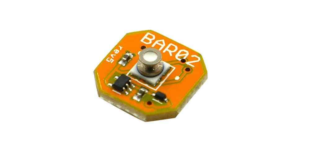
Stainless steel (metal) membrane has become an integral part of PCB pressure sensors, and it is there for a reason. The metal membrane, which is connected to the circuit board and the digital capacitive readout, is used to optimize the board’s performance.
Here is everything you need to know about the relationship between the metal membrane and the PCB.
1. Connection Methods
Several processes are used to connect or attach the metal membrane to the Printed Circuit Board (PCB). Among them are silver sintering, Transient Liquid Phase Bonding (TLP Bonding), and reactive joining.
Here is a breakdown of these different processes:
- Silver Sintering: based on diffusion, Silver (Ag) Sintering has to do with the interconnection of the metal membrane to the PCB, when the high-temperature resistance is up to 200˚C. As a way of facilitating and solidifying the bonding process, a higher pressure of up to 40 MPa is applied to the materials. Some of the advantages of this process are reduction of the total surface energy and serving as a better replacement for the high-melting soldering process.
- Transient Liquid Phase (TLP) Bonding: this has to do with the formation of intermetallic phases, based on diffusion processes. The primary application or use is for the microelectronic packaging for high-temperature applications. The advantage over other PCB pressure sensor processes is the melting point of the connecting alloy, which is higher than the bonding process’ temperature process.
- Electric Resistance Welding: this has to do with the melting and connection of two (2) metal parts. To get the best results in PCB pressure sensor, the process parameters, time and current have to be optimized to enable the welding of the metal membrane on the PCB’s metallization. This way, the risks of damaging the circuit board in the process will be greatly reduced.
- Reactive Joining: this is one of the processes for connecting the metal membrane to your PCB to help regulate the pressure sensor. It works by using an exothermal reaction, which aids the generation of the required heat. Once the heat is generated, a multilayer metal, the Reactive Foil (RF), will be placed or stacked between the two (2) layers of solder. Doing this aids the soldering procedure.
2. The Metal Membrane as an Alternative to the MEMS Pressure Sensors
The integration or the use of a capacitive pressure sensor with a metal membrane on the PCB became an option after the fallout in the workings of the MEMS pressure sensors.
The Microelectrochemical Systems (MEMS) pressure sensors are one of the important sensor technologies. Others include ceramic thick films and metal thin films.
The MEMS pressure sensors work by performing measurements of both very low pressure and of absolute pressure.
Although it outshines the metal thin pressure sensors with the measurement of absolute and low pressure, it does have some downsides. Some of the disadvantages include:
- The inability to measure higher pressure.
- Unsuitability for certain applications, especially those requiring a silicone gel or a transmission fluid.
Final Words
Based on the above submissions, the production of capacitive pressure sensors that attach to the PCB helps to reduce the need for complex housing, while saving costs.
