Soldering in PCB is the process of joining mechanical and electrical components together. Connections created should allow the free flow of electricity through the soldered joints. The quality of a soldered PCB hinges on the soldering approach and the quality of solder used.
Soldered PCB is the method by which small pieces are joined together on the surface layer. It could also mean the procedures of joining two or more electrical elements on the board. It is a vital step in the PCB manufacturing process.
Therefore, soldering affects the performance and viability of every electronic gadget and appliance. To ensure a defect free PCB, soldering wire to circuit board method and solder used must be of top standard.
Distortion or defect on the end product could arise from faulty soldered joints. Thus, in fabricating the PCB, the right choice of solder appropriate for the design is crucial.
This article will discuss ways to solder a wire to the PCB. The right equipment for PCB soldering and the steps required for the process.
Request Solder Wire to PCB, Pls Send Email to Sales@raypcb.com Now
What does Solder wire mean?
Solder is an element broadly used in the electronic manufacturing and technology industries. It helps to link elements and fasten them to a platform. Solder is a vital element in every electronic manufacturing process that includes soldering.
Solder also supplies both electrical and mechanical intersections on the board. Joining by solder ensures that each element is solidly fixed on the board instantly. As much as mechanical durability is crucial, so also are the electrical links. Ensure there’s an adequate supply of electricity by the soldered joints.
Solder wire is an acceptable type of solder. Its usage cuts across so many industries. Although, solder wires are not produced equally. This is due to its various suitability purposes. Each solder wires are for various appliances and temperatures.
There are different types of solder wires. The regular solder wire used in the electronic industry for soldering is a blend of lead and tin. It possesses a low liquefy point which could melt together with the soldering iron.
However, solder wires could either be in two various types. They include:
- Lead alloy solder wire
- Lead-free Solders
Lead Alloy Solder Wire
This is the most popular type of solder wire that contains metal lead and is viewed as the best. It is normally made out of alloy of lead and tin. Its mechanical and moist qualities make the lead based solder the most preferred. It is normally a combination of 60% tin and 40% lead at a melting point of 190⁰c. This implies a quick conversion between its liquefying and solid states.
Lead Free Solder
Lead based solder wire held the industry standard over time. However, lead’s health-related implications changed the status quo. This resulted in a drastic reduction in its choice and soldering wire price within a few years. The Lead free solder wire consists of copper, silver, and tin. The lead-free soldering wire price is friendly, unlike the lead based wires.
Lead free solder wire has a higher temperature of 217⁰C – 221⁰C melting point. It has played some vital roles in the reduction of the sizes of miniature gadgets. A highly compact board designed with lead-free solder wires has few faults. They hold the advantage over the lead based solder wire.
Soldering PCB Procedures
Soldering wire to circuit board could also mean the process of soldering electrical circuit boards. The process is apt for those whose desire is to work with electrical and electronic circuits. Though there are various means to completing this process, some basic tools required are alike. These basic tools include solder iron, solder, and other materials.
Soldering is an essential skill needed in assembling electronic circuits on the board. There are numerous ways to complete the process of soldering on the circuit board. However, the process is in two major ways. They include soft and hard soldering.
Soft Soldering
This deals with the fastening of small elements to the Printed circuit board. It deals with fixing small liquidized temperature elements to the circuit board. Tin lead alloy serves as the space cover metal. It also serves as the cohere instrument between the element and the circuit board. The heat source used for this kind of soldering is a gas torch which causes alloy breakdown.
Hard Soldering
Hard soldering uses solid solders to connect two various metallic components. It sprawls all over the holes of the elements unfastened due to intense heat. The hard soldering action plan consists of two alternate processes. They are silver soldering and brazing soldering. The space cover metal grasps a high temperature of 450⁰C.
Silver Soldering: This procedure is used to refine small elements as well as to perform abnormal fixing on the circuit board.
Brazing Soldering: This method of soldering means joining two ends on the base metal. The liquid filler helps join the two ends. Brass is the basic filling agent. It supplies an alliance through nuclear attraction and dispersal. Brazing soldering produces a very hard joint that connects the terminals.
Soldering Tools
Tools required to solder electronic components on the board vary. It is dependent on the exact category of design. There are basic tools required irrespective of what is to be soldered. They include:
Soldering Iron
The soldering iron is a basic requirement, which serves as the heat source to dissolve the solder. It is a palmtop device, pencil-shaped that entails various parts working together. These parts forge a pleasant, feasible, and workable tool. It is suitable for soldering electronic elements by hand.
Meanwhile, the majority of soldering irons are small in size. They exist in a bigger size called the solder gun. Irrespective of the size or shape of the soldering iron, they possess similar needed elements. The elements include:
- Solder Wick:It is the copper wire knitted together to take out additional solder not needed. It serves as the eraser.
- Tip:The tip on the soldering iron is the iron part that heats up and melts the solder. It touches the solder and controls it.
- Rest:Rest is the part of the soldering iron that guides the workplace from being destroyed by heat. It is not an iron though, but it provides a spot to place the iron to free the hands.
- Wand:The wand is part of the soldering iron that presents cushioned grip. It serves as cover from the heat produced from the iron. It is the handle of the soldering iron.
Request Solder Wire to PCB, Pls Send Email to Sales@raypcb.com Now
Solder Flux
Solder flux is the cleaning agent that helps in the removal of rust metal from the surface layer of the board. The flux helps to take out impurities from the conductors in PCB electronic processes. It serves in three different capacities in soldering.
- It helps to clean the soldering elements from being rusty
- Covers excess air that could have contact with the material. The excess could result in rustiness over a period of time.
- It enhances the oozing uniqueness of the solder itself
The impurities act as huge resistors to having an acceptable soldering joint on the PCB. Therefore, the importance of flux is enormous.
Types of fluxes used in soldering
RMA Type of flux
RMA is Rosin Mildly Activated Flux. It is suitable for places with a little high concentration of oxide on the PCB
R Flux
This type of flux is best for places where the oxidation is very minute. They are non-activated fluxes.
RA Flux
This Rosin Activated Flux is best suited for places with a very high concentration of oxide. Furthermore, the type of flux for soldering hinges on different parameters. These include the type of PCB, and equipment used, the type of components used, and the soldering machine.
Also, the environment is another factor that decides the type of flux. Fluxes could be in liquid soluble, this dissolves in the water without pollution. It could also come as no clean fluxes which do not require any cleaning after soldering.
Soldering Paste
Solder paste is the mixture of loose particles made up of metallic solder and adhesive. This is used to join different leads of cracked particles to connect ends on the PCB.
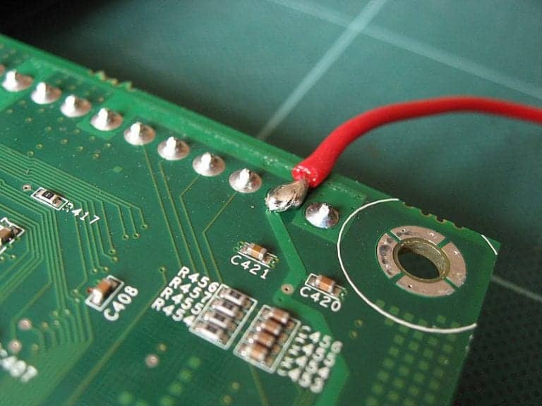
Steps to Soldering wire to the PCB
Attaching wires to the circuit board is through a process called soldering. The lead tin alloy is the solder wire type suitable for this process. The PCB pad and wire go through heating, while the solder wire melts until it flows into the pad and wire.
To solder wire to the Printed circuit board, the following steps are important
- Scrub the pad on which the wire will be joint on the PCB. Softly massage the erase till it becomes shiny and clean on the pad. Remove ¼ inch of cover from the wire.
- Put up the tip of the soldering iron by liquefying a fractional amount of the solder onto the iron point. Heat the wire tip with the soldering iron for seconds. Connect the solder wire to the exposed wire shortly until it melts the solder and flows to the free wires
- Slot the wire tip into the hole of the circuit board pad via the top side of the board. Curve the tip of the wire a bit to stop the wire from falling out when soldering. However, the wire should be well prevented from contact with any other pad on the board.
- Affix the soldering iron top to the wire tip and solder pad for some seconds until the wire tip melts.
- Apply fairly sufficient new solder to make a cupola shaped splash on the pad which shields the wire and hole. Take the iron from the pad but the board must not move for a minute.
- Cool off the soldered PCB joints. The board remains static until the solder solidifies. Cut off the wire tip using the wire cutters. The wire perpetually adheres to the printed circuit board.
Solder Jumper Wire on the Circuit Board
The electric wire that fixes two distant electric circuits on the board is the solder jumper wire. Also, it implies strong wires that connect points between two circuits without soldering.
It could be short-circuited and it could be a shortcut to the circuit when attached. Controlling of electricity on the board becomes practicable. While operating boards that do not use wiring as well could be controlled with the help of the solder jumper wire.
Solder jumper wires come in different colors. Though color is insignificant to its usage. The jumper wire is in three modes: male to male, female to female, and male to female. Their differences are at the endpoint of each. Male solder jumper wire has a pin end projected out while for the female it is basically used to plug things.
Why are the Solder Jumper wires Important to the PCB?
- You attach solder jumper wires to PCBs to allow connection on the board. The jumper wire is vital to the PCB for correction purposes. The Jumper wire helps in the correction of faults detected on the board or to execute a change as required on the assembly.
- The Jumper wire is a small copper wire added to the PCB. It is also considered a component. Soldering a jumper wire takes an automated form such as it is for other elements on the board.
- The jumper wire is also used as a hardware programming tool.
Conclusion
By now, you should know how to solder wire to pcb. Building electronic circuits such as the PCB requires choosing the right solder wire. Lead-free solder being a certified solder should be the most preferred. This is due to its low health hazard implication as compared to lead based wire.
It is important to note that adhering strictly to all safety standards is a requirement. This is to prevent the risk of fire, bodily injuries, and health hazards from toxic fumes. To fabricate a standard PCB, the quality of solder used is crucial. The type and quality of the solder wire used to connect components play vital roles to keep the standards high.
