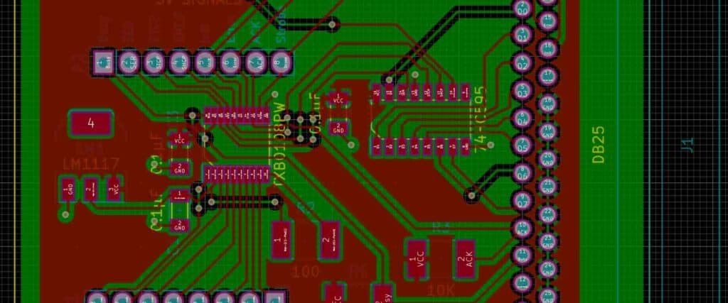
Water level indicators are essential for monitoring water levels in various applications such as tanks, wells, and reservoirs. In the past, water level indicators were made using mechanical components that were prone to wear and tear. However, advancements in technology have led to the development of water level indicator PCB layouts that are more reliable and efficient.
A water level indicator PCB layout is a circuit board that is designed to accurately detect the water level in a tank or reservoir. The PCB layout consists of various components such as sensors, resistors, and capacitors that work together to detect the water level and provide an output signal. The output signal can be used to trigger an alarm or control a pump to maintain the desired water level. With the use of a water level indicator PCB layout, it is possible to automate the process of monitoring and controlling water levels, which can save time and reduce the risk of human error.

PCB Layout
When designing a water level indicator PCB, the layout is a crucial aspect that must be taken into consideration. A well-designed PCB layout ensures proper functionality and reduces the chances of errors and malfunctions. Here are some important sub-sections to consider when designing a water level indicator PCB layout:
Components Placement
The placement of components on the PCB is essential for proper functionality. Components should be placed in a logical order to ensure that there is no interference between them. The placement should also consider the size of the PCB and the available space. It is recommended to start with the placement of the largest components and then move to the smaller ones.
Traces Routing
Traces routing is the process of connecting the components on the PCB. The routing must be done in a way that ensures that there is no interference between the components. It is recommended to keep the traces as short as possible to reduce the chances of noise and interference. The traces should also be wide enough to handle the required current.
Ground Plane
A ground plane is a large copper area on the PCB that is connected to the ground. It is essential for proper functionality and reduces the chances of noise and interference. The ground plane should be placed on the bottom layer of the PCB, and the traces should be routed on the top layer. The ground plane should be continuous, and there should be no gaps in it.
In conclusion, a well-designed PCB layout is crucial for the proper functionality of a water level indicator. The components should be placed logically, and the routing should be done in a way that ensures that there is no interference between them. The ground plane is also essential for reducing noise and interference.
Water Level Indicator Circuit

A water level indicator circuit is an electronic device that helps you monitor the water level in a tank or reservoir. It is a simple and cost-effective solution that can be easily installed to avoid water overflow or shortage. In this section, we will discuss the essential components of a water level indicator circuit.
Sensor Interface
The sensor interface is the heart of the water level indicator circuit. It consists of a set of probes that are placed at different levels in the water tank. These probes are connected to the PCB board, which measures the water level between the probes. The PCB board then sends a signal to the LED indicators to display the water level.
LED Indicators
The LED indicators are an essential part of the water level indicator circuit. They are used to display the water level in the tank. The circuit has three LED indicators, which indicate the water level as low, medium, or high. When the water level is low, the first LED glows, when it is medium, the second LED glows, and when it is high, the third LED glows.
Power Supply
The power supply is the source of energy for the water level indicator circuit. It is a DC power supply that can be either a battery or an adapter. The circuit requires a voltage of 5V to operate correctly. The power supply is connected to the PCB board, which regulates the voltage and supplies it to the LED indicators and the sensor interface.
In conclusion, the water level indicator circuit is a simple and effective solution to monitor the water level in a tank or reservoir. It consists of three essential components, the sensor interface, LED indicators, and power supply. The circuit can be easily installed and requires minimal maintenance.

