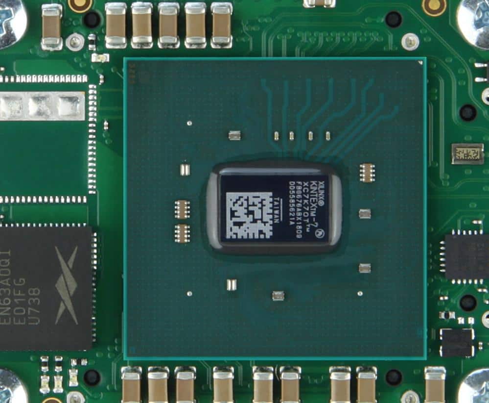
The Xilinx Kintex-7 FPGAs is known as one of the main product series which is built on a general architecture of 28nm. Furthermore, the design consumes the lowest power possible. In contrast with earlier FPGA generations, the power consumption of this family has a reduction of over 50%, while there is also an improvement in cost performance, about two 2 times.
Furthermore, the Xilinx Kintex-7 FPGAs can offer DSPs, logic of high density, memories, transceivers of high performance, and mixed flexible signals. Importantly, with these functions, you will be able to improve the performance of the system-level and also achieve tighter integration.
Features of Xilinx Kintex-7 FPGAs
The xilinx Kintex-7 FPGAs has the following features
- The xilinx Kintex-7 FPGA has a density that attains logic units of 2 million. This is about 2.5 times more compared to the existing and earlier FPGAs
- With this, you can also get the best balance regarding cost, power consumption, and performance of signal processing.
- It has a serial connection function of about 10.3125Gbps
- Abundant DSP resources and block memory
- Offers the required high performance for different applications like 10G high-volume optical wired equipment for communication
Xilinx Kintex-7 FPGAs Key Capabilities Overview
Reduction in cost, 2x the Price-Performance, Lower Cost
- Majority of innovations that boosts performance, which includes industry-leading memory interface of 1,866Mbps; DSP48E1 slices of 639MHz with high filtering capabilities; look-up table (six-input)
- memory interfaces of 1833Mbps
- 6G LVDS connectivity
- DSP slices of about 1,920
——————————————————————————————————————
Request Xilinx Kintex-7 FPGA Quote, Pls Send Files to Sales@raypcb.com Now
——————————————————————————————————————
Innovations for Memory Controller
- Hard and dedicated IP Memory Phy implementation. This ensures easy interfacing to the memory of the external DDR
- Soft and flexible controller made possible by logic of high-performance for system interfaces, access methods, and calibration
- PCI Express soft and hard IP of high-speed
- Hard IP that is integrated for PCI Express. It also has total support for the PCI Express root port and endpoint and configurations
- Also, it has hard IP support given to 8 PCI Express channels (Gen1 & Gen2)
Maximize the Connectivity and Stay Within the Budget
- The Xilinx Kintex-7 FPGAs allow designers to select a package using the right blend of performance and price for that application
- The family price indicates each throughput (12.5Gbps and 6.6Gbps transceivers)
- Maximize performance using regular BGA packaging flip-chips that offers the best possible signal integrity. Also, it attains about 32 GTX high-speed transceivers (line rates of 12.5Gbps)
- Reduce costs with flip-chip bare-die BGA packaging, which delivers a huge signal integrity as well as thermal features that are robust (line rates that reach about 6.6Gbps)
Consumption of Half the Power
- The process of the HPL reduces the power by half in contrast to the alternative High Performance process of 28nm
- Low voltage for the core at 1.0V core voltage (an optional core voltage alternative at 0.9V for some other devices) transforms into a lesser cooling, lesser system power, and higher “green” designs
- More power reductions gotten from clock gating and partial reconfiguration (fifth generation)
The AC and DC Switching Characteristics of the Xilinx Kintex-7 FPGAs
The Xilinx Kintex-7 FPGAs come in different speed grades, which includes -2L, -1L, -1, -2, and -3. The greatest performance of all is -3. Screening is usually done for devices working with the -2L speed grade for a reduced static power. Furthermore, in contrast to the -2 speed grade devices, they can function with cores of lower voltages to enjoy a reduced dynamic power.
The -2L speed grade industrial (I) devices function just at a VCCINT of 0.95V. Furthermore, the extended temperature devices working with the -2L speed grade can function at either a VCCINT of 1.0V or 0.9V.
Furthermore, anytime devices working with a speed grade of -2LE operate at a VCCINT of 1.0V, and devices working with a speed grade of -2LI operate at a VCCINT of 0.95V, they usually have similar speed specifications just like the speed grade of -2, except where it is noted.
Whenever any -2LE device operates at a VCCINT of 0.9V, there is a reduction in the dynamic power, static power, and speed specifications. The temperature devices of the military working with -1L speed grade feature similar speed specifications as the temperature devices of the military working with -1 speed grade. Furthermore, screening is done to achieve lower static power.
Also, the Kintex-7 FPGA AC and DC characteristics are seen in extended, military (-1M), commercial, expanded (-1Q), and industrial temperature ranges.
Asides from the operating range of temperature or unless noted otherwise, all the electrical parameters of the AC and DC have the same value for a specific speed grade. However, only some devices and/or speed grades come in each range of temperature.
Also, all junction temperature and supply voltage specifications represent worst-case conditions
Power Supply Power‐On/Off Sequencing
In order to achieve the lowest possible current draw and make sure that the 3-starting of the I/Os are done at power-on, then the appropriate power-on sequence you should work with is VCCO, VCCAUX_IO, VCCAUX, VCCBRAM, and VCCINT.
Also, the appropriate power-off sequence involves reversing the sequence of the power-on sequence. Let’s say that both the VCCBRAM and VCCINT feature a similar level of voltage, then you can power both by that same supply, which is then ramped simultaneously.
Also, if VCCO, VCCAUX_IO, and VCCAUX possess the same levels of voltage then you can power them up using that same supply, which is also ramped simultaneously.
In addition, for the 3.3V VCCO voltages in HR Input/Output banks, the difference in voltage between VCCAUX and VCCO must not surpass 2.625V in order to maintain the reliability levels of the device.
More on Power Supply Power‐On/Off Sequencing
Furthermore, you can allocate the TVCCO2VCCAUX time in any percentage falling between the power-off and power-on ramps. Also, in order to achieve the least current draw when working with GTX transceivers, the power-on sequence you should work with is VCCINT – VMGTAVCC – VMGTAVTT OR VMGTAVCC – VCCINT – VMGTAVTT.
Furthermore, for VMGTVCCAUX, no recommended sequencing exists. Also, you can ramp both the VCCINT and VMGTAVCC simultaneously. Furthermore, the power-off sequence that is recommended has to do with the power-on sequence’s reversal in order to get the minimum draw for the current.
If there’s failure in meeting the recommended sequences, then the current that is drawn or gotten from the VMGTAVTT could be more than the specifications during the power-down and powerup.
Also, when you power up VMGTAVTT before VMGTAVTT – VMGTAVCC and VMGTAVCC > 150 mV and also VMGTAVCC < 0.7V, then the current draw of the VMGTAVTT can rise by 460 mA for each transceiver during the ramping up of VMGTAVCC. The current draw duration can reach 0.3 x TMGTAVCC. For the power-down, the reverse holds true.
Moreover, When you power up VMGTAVTT before VMGTAVTT – VCCINT and VCCINT > 150 mV and also VCCINT < 0.7V, then the current draw of the VMGTAVTT can rise by 50 mA for each transceiver during the ramping up of VCCINT. The current draw duration can reach 0.3 x TVCCINT. For the power-down, the reverse holds true.
DC Output and Input Levels
The values for the VIH and VIL are the appropriate input voltages. The values for the IOH and the IOL are ensured over the required conditions for operation at the VOH and VOL test points. However, note that testing is only for selected standards.
Also, the choice is to make sure that the standards reach their specifications. Furthermore, the testing of these standards must be at a minimum VCCO. Also, this is done with the respective VOH and VOL levels of voltage shown. You sample test other standards.
——————————————————————————————————————
Request Xilinx Kintex-7 FPGA Quote, Pls Send Files to Sales@raypcb.com Now
——————————————————————————————————————
AC Switching Characteristics
The specification of the switching characteristics is done on the basis of per-speed-grade. Also, you can design them as Production, Preliminary, or advance. Let’s explain each of these designations:
Product Specification
The release of these specifications happens immediately the characterization of the required production silicon of a specific family member is done to offer complete correlation between the devices and specifications over lots of production lots.
Here, under-reporting of delays does not happen. Also, anytime there are changes, customers are given formal notification. Normally, the speed grades that are slowest usually get transition into production before the speed grades that are faster
Preliminary Product Specification
Regarding this specification, they work on full silicon characterization of the engineering sample. Furthermore, speed grades and devices having this designation have the intention to offer better indication of the silicon’s expected performance. Also, the chance that under-reporting delays happen is well reduced in contrast to the final product specification, known as Advance data.
Advance Product Specification
The Advance Product Specification works with only simulations and usually they are available after the freezing of the specifications of the device design. Although the speed grades coupled with the designation are seen as conservative and relatively stable, it is possible for some under-reporting to happen.
AC Switching Characteristics Testing
The derivation of the parameters for internal timing is from the measurement of the internal test patterns. Furthermore, all the AC switching characteristics usually represent worst-case voltage supply and conditions of junction temperature.
Designations of Speed Grade
Since the production of individual members of the family occurs at different times, migrating through different categories entirely depends on the fabrication status for every device.
Production Software and Silicon Status
There are cases whereby the release of a specific member of the family and speed grade goes to production before the release of the speed specification with the right label. However, if there is any discrepancy in the labeling, you can correct them in other releases for speed specification. Also, the listing of the speed and software specifications is the least releases necessary for production.
Picking the Right Voltage and Speed Grade in the Vivado Tools
When selecting a device, it is very necessary that you choose the right device voltage and speed grade while using the Vivado tools.
In order to choose the speed specification of 1.0V in the Vivado tools, pick the XA Kintex-7 sub-family, Defense Grade Kintex-7Q, and Kintex-7, and then choose the part name, which refers to the name of the device, then next is the name of the package and then the speed grade.
Furthermore, to choose the speed specifications of 0.95V (-2LI) for the Vivado tools, choose the Kintex-7 sub-family. Also, after this choose the name of the device, then the name of the package, and then the speed grade.
Also, to choose the speed specifications of -2LE (0.9V) in the Vivado tools, you have to pick the Kintex-7 Low Voltage, and then choose the name of the device (the part name), and then the name of the package, and lastly the speed grade.
What are the Kintex-7 FPGAs Devices?
The following are the Kintex-7 FPGAs Devices
XC7K410T-2FFG900I XC7K325T-2FFG900I XC7K410T-2FFG900C
XC7K325T-2FF900I XC7K325T-1FFG900C XC7K325T-1FFG900I
XC7K160T-1FBG676C XC7K70T-1FBG676I XC7K70T-2FBG484C
XC7K70T-1FBG676C XC7K480T-2FFG901C XC7K70T-1FBG484C
XC7K420T-2FFG901I XC7K410T-3FFG900C XC7K410T-3FFG900I
XC7K410T-2FFG676I XC7K410T-2FF676I XC7K410T-2FFG676C
XC7K410T-2FBG900I XC7K410T-2FBG676C XC7K410T-2FBG900C
XC7K410T-1FFG900I XC7K410T-1FBG676I XC7K410T-1FFG900C
XC7K325T-3FFG900I XC7K325T-3FFG676I XC7K325T-3FFG900C
XC7K325T-3FFG676C XC7K325T-2FFG676I XC7K325T-2FFG900C
XC7K325T-2FFG676C XC7K325T-2FBG676I XC7K325T-2FBG900I
XC7K325T-1FFG676I XC7K325T-1FBG900I XC7K325T-1FFG676C
XC7K325T-1FBG676I XC7K160T-2FFG676C XC7K160T-2FFG676I
XC7K160T-2FBG676I XC7K160T-2FB484I XC7K160T-2FBG484C
XC7K160T-1FFG676I XC7K160T-1FBG484I XC7K160T-1FBG676I
XC7K160T-1FBG484C XC7K325T-1FFG900CES XC7K325T-L2FFG676E
XC7K480T-L2FFG901I XC7K480T-L2FFG1156I XC7K480T-L2FFG901E
XC7K480T-3FFG901E XC7K480T-2FFV1156C XC7K480T-3FFG1156E
XC7K480T-2FF901C XC7K420T-L2FFG901E XC7K420T-L2FFV901E
XC7K420T-3FFG901E XC7K420T-2FFG1156I XC7K420T-3FFG1156E
XC7K410T-L2FFG900I XC7K410T-L2FFG676E XC7K410T-L2FFG676I
XC7K410T-L2FBG900E XC7K410T-L2FBG676E XC7K410T-L2FBG676I
XC7K410T-3FFG676E XC7K410T-3FBG676E XC7K410T-3FBG900E
XC7K410T-2FFV900C XC7K410T-2FBV676I XC7K410T-2FF900I
XC7K410T-2FB900I XC7K410T-1FF900C XC7K410T-1FF900I
XC7K410T-1FBG900I XC7K355T-L2FFG901I XC7K355T-L2FFV901E
XC7K355T-3FFG901E XC7K355T-1FF901I XC7K355T-2FFG901C
XC7K355T-1FF901C XC7K325T-L2FFG676I XC7K325T-L2FFG900I
XC7K325T-L2FBG900I XC7K325T-L2FBG676I XC7K325T-L2FBG900E
XC7K325T-L2FBG676E XC7K325T-3FBG676E XC7K325T-3FBG900E
XC7K325T-2FF900C XC7K325T-2FB676I XC7K325T-2FB900I
XC7K325T-1FFV900I XC7K325T-1FF676I XC7K325T-1FF900C
XC7K325T-1FB900I XC7K325T-1FB676I XC7K325T-1FB900C
XC7K325T-1FB676C
Now, let’s take a look at some of the technical data of four of these Xilinx Kintex-7 FPGAs Devices. These four can be used to generalize for the remaining 96 Kintex-7 FPGAs Devices.
XC7K410T-2FFG900I
Features of the XC7K410T-2FFG900I
- High-performance advanced FPGA logic, which is based on 6-input lookup table technology
- SelectIO high-performance technology that supports DDR3 interfaces to 1,866 Mb/s.
- Dual-port 36 Kb block RAM having an in-built FIFO logic to ensure buffering of on-chip data
- Also, is the Serial connectivity of high-speed with in-built transceivers from 600 Megabytes per second to a maximum rate of about 6.6 Gigabytes per second up to 28.05 Gigabyte per second
- An analog interface (XADC) that incorporates the 12-bit dual 1MSPS convertors (analog to digital) with on-chip supply and thermal sensors
- Also present are DSP slices having a 48-bit accumulator, 25 x 18 multiplier, and pre-adder. This ensures high-performance filtering. These includes symmetric optimized coefficient filtering
XC7K410T-2FFG900C
Features of the XC7K410T-2FFG900C
- DSP slices having a 48-bit accumulator, 25 x 18 multiplier, and pre-adder. This ensures high-performance filtering. These includes symmetric optimized coefficient filtering
- Powerful CMT (clock management tiles) that combines MMCM (mixed-mode clock manager) and PLL (phase-locked loop) to ensure low jitter and high precision
- Serial connectivity of high-speed with in-built transceivers from 600 Megabytes per second to a maximum rate of about 6.6 Gigabytes per second up to 28.05 Gigabyte per second
XC7K325T-2FFG900I
Features of the XC7K325T-2FFG900I
- An analog interface (XADC) that incorporates the 12-bit dual 1MSPS convertors (analog to digital) with on-chip supply and thermal sensors
- PCI Express integrated block for up to eight times Gen3 Root Port and Endpoint designs
- Also present are different configuration options, which include in-built SEU correction and detection, commodity memories support, and more
- Also present are DSP slices having a 48-bit accumulator, 25 x 18 multiplier, and pre-adder. This ensures high-performance filtering. These includes symmetric optimized coefficient filtering
- Powerful CMT (clock management tiles) that combines MMCM (mixed-mode clock manager) and PLL (phase-locked loop) to ensure low jitter and high precision
——————————————————————————————————————
Request Xilinx Kintex-7 FPGA Quote, Pls Send Files to Sales@raypcb.com Now
——————————————————————————————————————
XC7K325T-2FF900I
Features of the XC7K325T-2FF900I
- High-performance advanced FPGA logic, which is based on 6-input lookup table technology
- Also present is a dual-port 36 Kb block RAM having an in-built FIFO logic to ensure buffering of on-chip data
- SelectIO high-performance technology that supports DDR3 interfaces to 1,866 Mb/s.
- An analog interface (XADC) that incorporates the 12-bit dual 1MSPS convertors (analog to digital) with on-chip supply and thermal sensors
- Also present are DSP slices having a 48-bit accumulator, 25 x 18 multiplier, and pre-adder. This ensures high-performance filtering. These includes symmetric optimized coefficient filtering
- Different configuration options, which include in-built SEU correction and detection, commodity memories support, and more
Benefits of the Xilinx Kintex-7 FPGAs
Best Price-Performance of the Industry
After the introduction of the first 28nm FPGAs, designers have the widest possible range of platforms that are programmable, which includes the new devices’ versatility. When you double the price performance, and then reduce the cost and power consumption in half, this ensures that the Xilinx Kintex™-7 FPGAs stand out as the best option for the quick-growth applications of today like wireless communications.
With these great features, designers will be able to make use of these devices with exceptional connectivity and performance, at a price point that was initially limited to just applications with the highest-volume.
High-Speed, Highly Integrated Connectivity
With the Xilinx Kintex-7 FPGAs, designers will be able to build in a much better bandwidth and a 12-bit analog that is digitally programmable, coupled with meeting power and cost requirements.
Unequalled 144GMACS DSP power transforms these versatile Xilinx Kintex-7 FPGAs into the best possible option for different applications like next-generation communications and portable or small ultrasound equipment.
Furthermore, all Xilinx Kintex-7 FPGAs offer a high serial bandwidth of 800 Gbps. These include IP cores of CPRI/OBSAI (9.8Gbps), which has been optimized for the baseband architectures of today. Also, these programmable Xilinx Kintex-7 FPGAs can be reconfigured with ease. This is to offer some support for many air interfaces like WCDMA, WiMAX, and LTE. In order to interface to the host systems, the Xilinx Kintex-7 FPGAs offer in-built support for 8 channels of the Gen1/Gen2 (PCI Express).
The highly affordable and efficient devices also make it possible for the designers to check throughput and connectivity requirements while reducing the part counts. Also, the 1,833Mbps, 72-bit memory interface of the Kintex-7 supports a single memory for the buffer designs rather than use two or four buffer designs that are usually required by other devices.
Importantly, one single Kintex-7 device has the ability to handle rates, which allows the implementation of a single chip over IP gateway, which can back 12 channels using 3G over an Ethernet bridge with 10 Gigabit and 4-channels.
The Unified Architecture’s Strength
All the seven series FPGA families usually leverage the unified architecture. This is just to offer some protection for IP investments thereby making migration of six series designs much easier. Using common elements such as Block RAM, logic fabric, clocking, DSP, AMS, etc, also the unified architecture helps in facilitating quick retargeting within these 7 series. Also, for new projects and migrations, the architecture of the Kintex-7 helps in reducing the development times dramatically. This also assists designers to put their attention on the product differentiation.
Maximizing Productivity Using the Targeted Platforms for Design
Xilinx Targeted Platforms for design are the best development kits for the industry, which are complete with tools, boards, reference designs, IP cores and FMC support. With these kits, designers can immediately start the development of the application. It also boosts productivity while speeding up the advanced functionality access with reference designs that are pre-verified.
Furthermore, in combination with an evaluation board with full features and the Design Suite software, this facilitates the incorporation of solutions from ecosystems of available add-on third-party IP and hardware.
In addition, the Xilinx Kintex base kit (KC705 Evaluation Kit), offers a framework that is flexible for the design of systems with higher-level, which require PCI Express, Gigabit Ethernet, DDR3, as well as other serial connectivity. Also, the Kintex-7 FPGA DSP Kit, which is the 1st domain kit, features a high-speed, integrated analog FMC, which helps in interfacing to the real-world signals.
The Xilinx Kintex-7 FPGAs provide the most appropriate price-performance. This helps designers in meeting strict latency requirements for the processing of LTE baseband in common platforms.
- The programmability allows for a common and cost-effective platform offering support for many air interfaces like WCDMA, WiMAX, and LTE
- Reduction in the ownership’s total cost having the capability to reuse and scale designs from macrocell to picocell and vice-versa
- Three times capacity at a cost same as the initial-generation FPGAs during the consumption of 40% power less
- Offers support for 9.8Gbps OBSAI/ CPRI for any high throughput
- Offers support for 6.144Gbps OBSAI/CPRI in the low-cost package alternative
Conclusion
We hope we have been able to explain to you what the Xilinx Kintex-7 FPGAs offer. Furthermore, they have great features and their significance in the technology world cannot be overemphasized. Also, if you still have some points you need some clarification on, please send us a message. We will respond to it as fast as we can.
