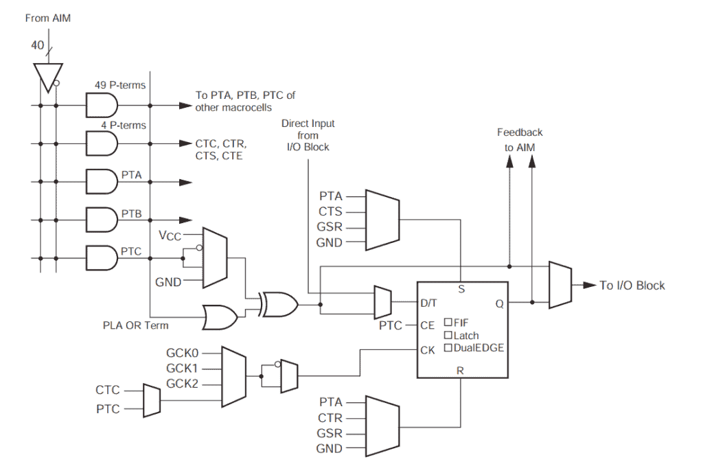
Digital logic is a fundamental concept in the field of computer science and engineering. It refers to the study of electronic circuits that process digital signals, which are represented as binary values of 0 and 1. These circuits form the building blocks of modern computers, and understanding digital logic is essential for anyone who wants to design or work with computer hardware.
At its core, digital logic involves the manipulation of binary values using logical operations such as AND, OR, and NOT. These operations can be combined to create more complex circuits that perform various functions, from simple arithmetic to complex data processing. Digital logic circuits can be implemented using a variety of electronic components, including transistors, diodes, and logic gates.
Whether you’re a computer science student, an electrical engineer, or simply someone who wants to understand how computers work, a solid understanding of digital logic is essential. By mastering the fundamentals of digital logic, you’ll be able to design and build your own electronic circuits, troubleshoot problems with existing circuits, and gain a deeper understanding of the inner workings of modern computers.

Boolean Algebra
Boolean algebra is a branch of algebra that deals with variables that can only take on two values, typically represented as 0 and 1. It is named after George Boole, who developed the algebraic system in the mid-19th century. Boolean algebra is widely used in digital logic design and computer programming.
Boolean algebra is based on three main operations: AND, OR, and NOT. These operations can be represented using truth tables, which show the output of the operation for every possible combination of input values. For example, the truth table for the AND operation is:
| A | B | A AND B |
|---|---|---|
| 0 | 0 | 0 |
| 0 | 1 | 0 |
| 1 | 0 | 0 |
| 1 | 1 | 1 |
In this table, A and B are input variables, and A AND B is the output of the AND operation.
Boolean algebra also includes several laws and rules that can be used to simplify expressions. Some of the most common laws include:
- Commutative law: A AND B = B AND A, A OR B = B OR A
- Associative law: (A AND B) AND C = A AND (B AND C), (A OR B) OR C = A OR (B OR C)
- Distributive law: A AND (B OR C) = (A AND B) OR (A AND C), A OR (B AND C) = (A OR B) AND (A OR C)
- De Morgan’s laws: NOT (A AND B) = (NOT A) OR (NOT B), NOT (A OR B) = (NOT A) AND (NOT B)
By applying these laws and rules, complex expressions can be simplified and optimized for digital logic circuits.
In conclusion, Boolean algebra is a fundamental concept in digital logic design and computer programming. It provides a powerful framework for working with binary variables and simplifying complex expressions.
Logic Gates

Logic gates are the fundamental building blocks of digital circuits. They are electronic circuits that perform basic logical operations such as AND, OR, and NOT. These operations are based on Boolean algebra, which is a mathematical system that deals with logic and truth values.
There are several types of logic gates, each with its own unique function. Here are some of the most common ones:
-
AND gate: This gate produces a high output only when all of its inputs are high. Otherwise, it produces a low output.
-
OR gate: This gate produces a high output when any of its inputs are high. It produces a low output only when all of its inputs are low.
-
NOT gate: This gate produces the opposite of its input. If the input is high, the output is low, and vice versa.
Logic gates can be combined to create more complex circuits. For example, a combination of AND and OR gates can be used to create a circuit that performs the logical operation known as NAND (NOT AND). Similarly, a combination of OR and NOT gates can be used to create a circuit that performs NOR (NOT OR).
Logic gates are typically represented using symbols. These symbols are used to create circuit diagrams, which are graphical representations of electronic circuits. Here are some examples of logic gate symbols:
-
AND gate: The symbol for an AND gate is a triangle with a dot on the output side and two inputs on the other side.
-
OR gate: The symbol for an OR gate is a circle with a plus sign on the output side and two inputs on the other side.
-
NOT gate: The symbol for a NOT gate is a triangle with a small circle on the output side and a single input on the other side.
In summary, logic gates are the basic building blocks of digital circuits. They perform logical operations based on Boolean algebra and are represented using symbols. By combining logic gates, more complex circuits can be created.
Combinational Logic

Combinational logic is a type of digital logic that produces an output based on the input. The output is determined by the combination of input values, and there is no memory or feedback involved. Combinational logic circuits can be designed using logic gates such as AND, OR, NOT, and XOR gates.
One of the most common applications of combinational logic is in arithmetic circuits. For example, a binary adder is a combinational logic circuit that adds two binary numbers together. The circuit uses a series of logic gates to perform the addition operation and produce the sum.
Combinational logic circuits can also be used for other applications such as decoding, multiplexing, and demultiplexing. A decoder is a combinational logic circuit that converts a binary code into a set of output signals. A multiplexer is a combinational logic circuit that selects one of several input signals and forwards it to a single output. A demultiplexer is a combinational logic circuit that takes a single input signal and forwards it to one of several possible outputs.
In summary, combinational logic is a fundamental concept in digital logic that produces an output based on the input. It is used in a wide range of applications, including arithmetic circuits, decoding, multiplexing, and demultiplexing.
Sequential Logic

Sequential logic is a type of digital circuit that is used to store information. Unlike combinational logic, which is only concerned with the current inputs, sequential logic circuits take into account previous inputs and outputs.
Sequential logic circuits use feedback to store information. The feedback loop allows the output of the circuit to be fed back into the input, which can then be used to determine the next output. This feedback loop is what allows sequential logic circuits to store information and perform more complex operations.
There are two main types of sequential logic circuits: synchronous and asynchronous. Synchronous circuits use a clock signal to synchronize the inputs and outputs. Asynchronous circuits do not use a clock signal and instead rely on the inputs and outputs to trigger the circuit.
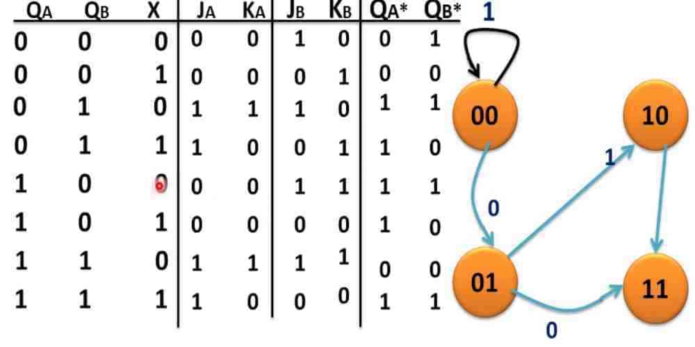
One of the most common types of sequential logic circuits is the flip-flop. Flip-flops are used to store a single bit of information and can be combined to create more complex circuits. There are several types of flip-flops, including D flip-flops, JK flip-flops, and T flip-flops.
Another important component of sequential logic circuits is the shift register. Shift registers are used to store multiple bits of information and can be used for serial-to-parallel and parallel-to-serial conversions.
Overall, sequential logic circuits are an essential component of digital electronics. They allow for the storage and manipulation of information and are used in a wide range of applications, including computer memory and control systems.

