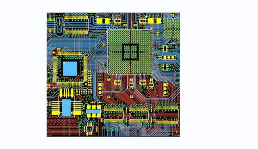
A printed circuit board (PCB) is an essential component of any electronic device. It provides a platform for all the electronic components to be connected and work together. PCB layout design is crucial to ensure that the electronic components are connected correctly and efficiently. In this article, we will discuss the PCB layout of a 5V power supply.
A 5V power supply is a common requirement for many electronic devices, including microcontrollers, sensors, and other digital circuits. The PCB layout of a 5V power supply is critical to ensure that the circuit functions correctly and efficiently. The layout should be designed to minimize noise, reduce heat buildup, and ensure that the power supply can provide a stable and consistent output voltage. In the following paragraphs, we will discuss the essential elements of a 5V power supply PCB layout and how to design it effectively.

PCB Layout Basics
When designing a PCB layout for a 5V power supply, there are a few basic principles to keep in mind. These include component placement and trace routing.
Component Placement
The placement of components on a PCB is critical to the performance and reliability of the circuit. It is important to place components in a way that minimizes noise and interference while maximizing efficiency and heat dissipation.
To achieve this, it is recommended to:
- Group components according to their functions
- Place high-frequency components close to the power source
- Place heat-generating components away from sensitive components
- Keep traces as short as possible
Trace Routing
Trace routing is the process of connecting components on a PCB using copper traces. The routing of these traces can have a significant impact on the performance and reliability of the circuit.
When routing traces for a 5V power supply, it is important to:
- Keep traces as short as possible to minimize resistance and voltage drop
- Use wider traces for high-current components to minimize heat generation
- Avoid crossing traces to minimize interference and noise
- Use ground planes to minimize noise and interference
By following these basic principles of PCB layout, you can ensure that your 5V power supply is efficient, reliable, and performs as expected.
5V Power Supply Design

Power Requirements
When designing a 5V power supply, it is important to carefully consider the power requirements of your specific application. This includes determining the maximum current draw of your circuit and selecting components that can handle that load.
To calculate the maximum current draw, add up the current requirements of all components in your circuit. It is also important to consider any potential spikes in current that may occur during operation.
Voltage Regulation
In order to maintain a stable 5V output, voltage regulation is essential. This can be achieved through the use of a voltage regulator, such as the LM7805.
When selecting a voltage regulator, it is important to consider the maximum input voltage and the maximum current output. Additionally, it is important to ensure that the regulator is properly heatsinked to prevent overheating.
In addition to voltage regulation, it may also be necessary to filter the output of the power supply to reduce noise and ripple. This can be achieved through the use of capacitors and inductors.
Overall, careful consideration of power requirements and voltage regulation is essential when designing a 5V power supply. By selecting the appropriate components and implementing proper filtering techniques, a stable and reliable power supply can be achieved for your application.
Grounding and Decoupling
Ground Plane
Grounding is a critical aspect of PCB layout for a 5V power supply. It ensures that the different components are at the same potential and that the circuit functions correctly. A ground plane is a large area of copper on the PCB that serves as the reference for the circuit. It is typically located on the bottom layer of the board and connected to the ground pin of the power supply. The ground plane should be as large as possible to reduce the impedance of the circuit.
Decoupling Capacitors
Decoupling capacitors are used to filter out high-frequency noise and voltage spikes that can disrupt the circuit. They are placed as close as possible to the power pins of the components they are protecting. The capacitors should be selected based on the frequency range of the noise they are expected to filter out. A good rule of thumb is to use a 0.1uF ceramic capacitor for each integrated circuit.
When designing the PCB layout, it is important to place the decoupling capacitors in strategic locations to minimize the length of the traces between the capacitor and the component. This reduces the inductance of the circuit and improves the effectiveness of the capacitor. It is also important to use multiple capacitors of different values to cover a wide range of frequencies.
In summary, proper grounding and decoupling are critical for the successful operation of a 5V power supply. A ground plane should be used to provide a low impedance reference for the circuit, and decoupling capacitors should be placed as close as possible to the power pins of the components they are protecting. By following these guidelines, the circuit will be more stable and reliable.
Thermal Management

Heat Dissipation
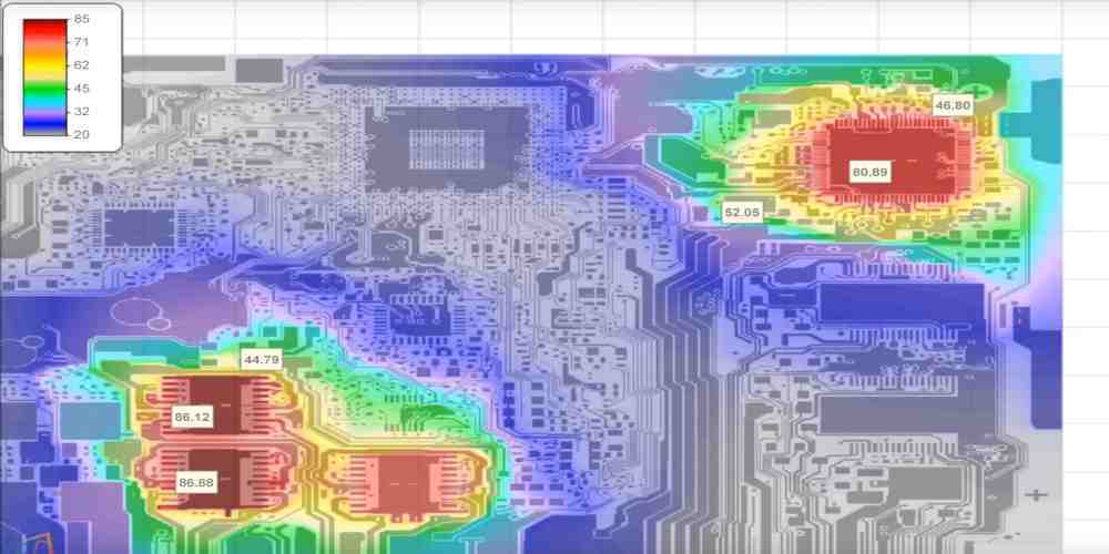
One of the most important aspects of designing a 5V power supply PCB layout is thermal management. The heat generated by the power supply components can cause damage to the board and affect the performance of the power supply. Therefore, it is essential to dissipate the heat effectively.
To achieve this, it is recommended to use a copper pour on the PCB to create a heat sink. The copper pour should be connected to a ground plane to provide better heat dissipation. Additionally, placing thermal vias on the PCB can also help to dissipate heat.
Thermal Relief
Another important aspect of thermal management is thermal relief. Thermal relief is the process of reducing the thermal stress on the PCB due to temperature changes. This can be achieved by using thermal relief pads for components that generate a lot of heat.
Thermal relief pads are designed to provide a connection to the component while minimizing the amount of copper around the pad. This reduces the amount of heat that is transferred to the PCB, which in turn reduces the thermal stress on the board.
In conclusion, effective thermal management is critical to the performance and longevity of a 5V power supply PCB layout. By using copper pours, thermal vias, and thermal relief pads, the heat generated by the power supply components can be dissipated effectively, reducing the risk of damage to the board and ensuring the optimal performance of the power supply.
Conclusion
In conclusion, designing a PCB layout for a 5V power supply can be a complex process, but it is essential to ensure the reliability and safety of the circuit. By following best practices and guidelines, such as keeping traces as short as possible, using appropriate component placement, and avoiding ground loops, you can create a robust and efficient power supply.
It is also important to consider the thermal management of the circuit, as excessive heat can damage components and reduce the lifespan of the power supply. Using thermal vias and heat sinks can help dissipate heat and improve the overall performance of the circuit.
When selecting components for the power supply, make sure to choose high-quality parts from reputable manufacturers. Using low-quality components can result in unreliable operation and potential safety hazards.
Finally, testing and validating the PCB layout is crucial before deploying the power supply in a real-world application. This includes verifying the output voltage and current, checking for any noise or interference, and ensuring the circuit operates within safe temperature limits.
By following these guidelines and best practices, you can design a reliable and efficient PCB layout for a 5V power supply that meets the requirements of your application.

