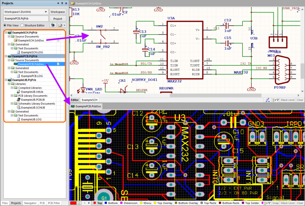
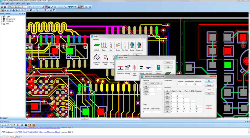
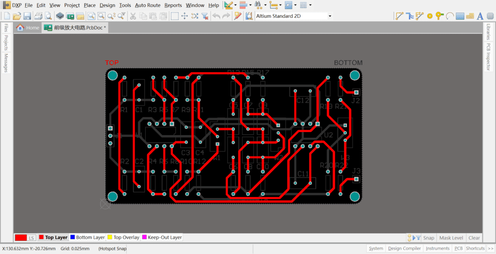
Board level annotation is a critical aspect of the printed circuit board (PCB) design process. It involves adding notes, comments, and symbols to the PCB design to provide additional information to the manufacturer, assembler, and tester. Board level annotation ensures that the PCB is manufactured correctly, assembled properly, and tested accurately.
Altium is a software tool that supports board level annotation. It provides a comprehensive set of annotation features that enable designers to add notes, comments, and symbols to their PCB designs quickly and easily. Altium also allows designers to customize the annotation process to meet their specific needs, including the ability to add custom symbols and text.
With Altium, designers can annotate their PCB designs at any stage of the design process, from the initial schematic to the final layout. This flexibility allows designers to catch errors and make changes early in the design process, reducing the risk of costly mistakes and delays. Overall, Altium’s board level annotation capabilities make it an essential tool for any PCB designer looking to create high-quality, error-free designs.

Overview of Board Level Annotation in Altium
What is Board Level Annotation?
Board level annotation is the process of adding notes, labels, and other information to a PCB design to make it easier to understand and manufacture. Board level annotation in Altium involves adding designators, names, and values to components, nets, and other objects on the PCB.
Why is Board Level Annotation important?
Board level annotation is important for several reasons. First, it helps designers keep track of the different components and nets in their design. By adding designators and names to components and nets, designers can quickly identify what each item is and where it is located on the board.
Second, board level annotation is important for manufacturing. When a PCB design is sent to a manufacturer, the manufacturer needs to know what each component is and where it is located on the board. By adding designators and names to components, designers can ensure that the manufacturer can easily identify each component and place it correctly on the board.
Finally, board level annotation is important for debugging and testing. When a PCB design is being tested, it is important to be able to quickly identify each component and net in the design. By adding designators and names to components and nets, designers can quickly identify the source of any issues or problems that arise during testing.
In conclusion, board level annotation is a critical part of the PCB design process. By adding designators, names, and values to components and nets, designers can ensure that their designs are easy to understand, manufacture, and test.
Creating Board Level Annotation in Altium

Step 1: Setting up the Annotation Layer
Before you start creating board level annotation in Altium, you need to set up the annotation layer. To do this, you can follow these simple steps:
- Open the PCB document in Altium.
- Go to the “Layers” tab and click on “Add Layer”.
- Select “Mechanical” as the layer type and “Annotation” as the subtype.
- Choose a name for the annotation layer and click “OK”.
Step 2: Adding Annotation to Components
Once you have set up the annotation layer, you can start adding annotation to your components. Here’s how:
- Select the component you want to annotate.
- Right-click on the component and select “Properties”.
- In the “Comment” field, enter the annotation text.
- In the “Designator” field, enter the designator for the component.
- Click “OK” to save the changes.
You can repeat these steps for each component you want to annotate.
Step 3: Updating Annotation
If you need to update the annotation for a component, you can follow these steps:
- Select the component you want to update.
- Right-click on the component and select “Properties”.
- Update the annotation text or designator as needed.
- Click “OK” to save the changes.
Altium will automatically update the annotation on the annotation layer.
In conclusion, creating board level annotation in Altium is a simple process that can be done in just a few steps. By following the steps outlined above, you can easily add and update annotations to your components.
Customizing Board Level Annotation in Altium

Changing Annotation Font and Size
Board-level annotation is a critical aspect of PCB design, and Altium provides users with a variety of options to customize the annotation to meet their needs. One of the most basic ways to customize board-level annotation in Altium is by changing the font and size.
To change the font and size of board-level annotation in Altium, users can follow these simple steps:
- Select the annotation object that needs to be modified.
- In the Properties panel, click on the Font button.
- Select the desired font and size from the Font dialog box.
- Click OK to apply the changes.
Customizing Annotation Style
In addition to changing the font and size, users can also customize the style of board-level annotation in Altium. This includes modifying the color, line thickness, and other visual aspects of the annotation.
To customize the style of board-level annotation in Altium, users can follow these simple steps:
- Select the annotation object that needs to be modified.
- In the Properties panel, click on the Appearance button.
- Select the desired style options from the Appearance dialog box.
- Click OK to apply the changes.
Creating Custom Annotation Templates
Finally, users can create custom annotation templates in Altium to streamline the annotation process and ensure consistency across multiple PCB designs. This can be particularly useful for companies with multiple designers working on different projects.
To create a custom annotation template in Altium, users can follow these simple steps:
- Create a new PCB document.
- Add the desired annotation objects to the document.
- Customize the font, size, and style of the annotation objects as desired.
- Save the document as a template.
By following these simple steps, users can customize board-level annotation in Altium to meet their specific needs and streamline the PCB design process.
Best Practices for Board Level Annotation in Altium

Consistency and Clarity
When annotating your PCB design in Altium, consistency and clarity are key. It’s important to establish a clear and consistent system for labeling components, nets, and other design elements. This will make it easier to read and understand your design, both for yourself and for others who may need to work with it.
One way to ensure consistency is to use a standardized naming convention for your components and nets. For example, you might use a prefix to indicate the type of component (e.g. R for resistors, C for capacitors, etc.) and a numbering system to distinguish between individual components of the same type. Similarly, you might use a consistent naming convention for nets, such as using the name of the signal or function they carry.
Another important aspect of clarity is to ensure that your annotations are legible and easy to read. This may involve choosing a font that is clear and easy to read at small sizes, and using appropriate font sizes and styles for different types of annotations.
Avoiding Overcrowding and Clutter
While it’s important to provide clear and detailed annotations, it’s also important to avoid overcrowding your design with too much information. This can make it difficult to read and understand, and can also make it harder to make changes or modifications to the design later on.
One way to avoid overcrowding is to use hierarchical annotations, which allow you to group related components and nets together and provide a higher-level overview of the design. This can make it easier to navigate and understand the design as a whole, while still providing detailed information when needed.
Another way to avoid clutter is to use color coding and other visual cues to help distinguish between different types of annotations. For example, you might use different colors to indicate different types of components or nets, or use bold or italic text to highlight important information.
Using Annotation as a Design Tool
Finally, it’s worth noting that annotations can be more than just a way to document your design – they can also be a powerful design tool in their own right. By using annotations to provide feedback and guidance during the design process, you can ensure that your design meets your requirements and specifications, and identify potential issues or areas for improvement early on.
For example, you might use annotations to indicate areas where components are too close together, or where there are potential signal integrity issues. By addressing these issues early on, you can avoid costly and time-consuming rework later in the design process.
Overall, effective board level annotation in Altium requires a balance between consistency, clarity, and usability. By following these best practices and using annotations as a design tool, you can create designs that are easy to read, understand, and modify, while also ensuring that they meet your requirements and specifications.

