A contemporary and the increasingly sophisticated electronic world demands a high-performing and flexible PCB. Electronic designers have to understand the nuances and intricacies of flexible PCB, including design consideration, fabrication, and application areas. It becomes essential in addressing the typical electronic challenges and needs. So what does it all entail?
What is Flexible PCB?
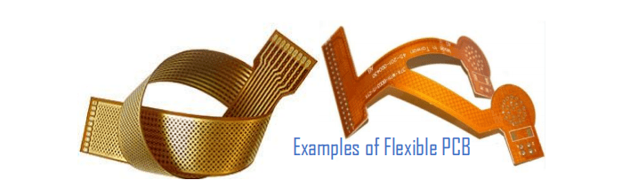
First flexible PCB is also called flex circuits and flex prints. This type of circuit board can be bent into whatever shape you desire. Also, they serve high-temperature and high-density applications.
Furthermore, these flex designs are made up of a polyester film (transparent) or polyimide as its substrate material, which features a high resistance of heat. This makes it great for any solder mounting component.
Flex circuits feature a layer of traces which is composed of copper combined with a dielectric layer made of polyimide. The copper layer’s thickness varies between 0.0001” and 0.010” while the dielectric material’s thickness ranges between 0.0005 and 0.010 inches.
Also, there’s a need for an adhesive to bond the layer of conductive copper to the substrate. In addition, the choice of material for the making of flex circuits may come tricky and this is dependent on so many factors. These factors include temperature, current, mechanical and chemical resistance, and flexing types.
A flexible design is more reliable. This is because they feature fewer interconnections, which ensures fewer contact crimps and solder joints. Also, these circuits usually require a reduced space as a result of their flexible bending capability. Furthermore, they only cover 10% of the required area in contrast to the rigid circuits.
Flexible PCB Structure
The structure of a flexible circuit board is always instrumental for engineers when designing flexible PCB. Like rigid printed circuit boards, we can classify the flexible PCB as multilayer, double layer, or single-layer circuits. While the number of layers can distinguish one flexible PCB from the other, the core structure mostly always remains the same save for the additional layers.
A single layer flex PCB contains the dielectric film as its base material. The material is primarily composed of polyimide that comes highly resistant to temperature and traction. Another critical element of the structure entails the electrical conductors consisting of copper. It represents the circuit traces and is instrumental in signal transmission. Protective finish is also a vital element of the flex PCB structure and comprises of a coverlay or coat. The adhesive material concludes the last aspect of the single layer fpc structure. It gets consisting of epoxy resin or polyethylene.
The copper gets etched to get traces, while the protective coating gets drilled to permit the solder pads. Such components joined together with the dielectric substrate from the single-layer flex PCB. However, as the complexity and components increase, the need for more layers becomes apparent. Here, based on the number of components and complexity of the circuits, a designer either picks a double layer fpc or a multilayer flex PCB.
One structural difference between a single layer and multilayer flex PCBs involves the PTH (plated through-hole). The PTH connects the different conductive layers of the flexible circuit board. Additionally, the adhesive material joins the dielectric substrate with the conductive tracks.
What is the Manufacturing Process of Flex Circuits?
When manufacturing flex circuits, the substrate material used is Polyimide. This material, in contrast to the FR-4, is more expensive. This is why you need to be careful when using it. In order to use this polyimide material appropriately, you have to use the nesting technique so as to ensure that these circuit boards are kept close.
Below are the steps involved in the manufacturing of flexible PCBs.
Looping
With the service loop, this ensures the circuit assembly and servicing length which is the extra material added beyond the limit of the designer.
Sizing Conductor
For the conductive material used on the circuit board, thin copper is very useful. It is responsible for the flexibility of the circuit. Also, it makes it appropriate for any dynamic application.
Etching
Etching is useful for the compensation of isotropic losses all through the process of manufacturing. For this process, the thickness of the copper foil is half the loss of the line width. The line width is affected by some factors, which includes etch mask, conductor, and different conductor types.
Routing
The routing is easy. With routing, there is a reduction in stress and great improvements in the folding and bending.
Ground Planes
The creation of ground planes helps in reducing the board’s weight and ensures better flexibility of the circuit board. Next, the creation of holes is very important before you apply fileting whereby the pad area can be increased in order to divide the stress.
Furthermore, there’s a need for the application of the liquid screen-printable overcoats before you go ahead to add film polymers and photo imaginable liquids, which serves as solder masks and prevents a circuit from both external and internal damages.
What are the Types of Flex Circuits?
There are four major types of flex circuits or flexible PCBs. Let us consider them.
Single Layer Flex Circuits
From the name, we can easily define it as a flexible PCB having a single conductive layer, which sits on a dielectric film that is flexible. Also, its electric components rest on just one of the sides of the printed circuit board
Double Layer Flex Circuits
A double-layer flexible PCB features a conducting layer on the two sides of the printed circuit board. This allows PCB engineers and manufacturers to connect the electrical components on any of the conductive layer sides.
Multiple Layer Flex Circuits
This type of flexible PCB features at least three conductive layers. These layers are separated with the help of a dielectric material. With irregular lamination, there is a high flexibility of the board as well as a lamination thickness, which is usually less in the area for bonding.
HDI Flex Circuits
HDI here means high-density interconnect. This circuit design is reliable, efficient, and features a better layout, construction, and design in contrast to other circuit boards. In addition, the HDI flex circuits provide an effective electrical performance, as well as a reduction in package size as a result of a thinner material for the substrate which are useful in manufacturing these boards.
This combines both the features of the flexible and rigid circuit boards, which offer a higher density forn the components, in contrast to other types of circuit boards.
Advantages of Flexible PCB
Flexible PCBs offer several advantages. Due to these advantages, these boards are a great option for some applications. The benefits of flex circuit include:
Reduced assembly time and cost
Flexible PCB assembly requires less manual labor. Therefore, this helps to reduce production errors and reduce assembly time. The assembly process of flexible PCB requires the use of machines. Also, flex circuits can form and fit well. These circuits eliminate the need for routing and soldering wires. Also, flexible PCBs eliminate wiring errors. Therefore, this helps to reduce the cost of manufacturing.
High density applications
Flexible PCBs enable narrow spaces and lines. Therefore, this gives room for a high density device population. Also, these circuits allow lighter conductors and denser device population in an electronic device. In the long run, this provides space for additional product features.
Design flexibility
A flex circuit isn’t restricted to just two dimensions. This is because this circuit is as flexible as ribbon cables or wires. Also, there are many design options for flexible circuit boards. These boards can meet the demands of complex configurations.
Increased heat dissipation
Due to the presence of polyimide dielectric, this board can withstand extreme high temperatures. Also, flex circuits dissipate heat generated in traces. This is because of the larger surface-to-volume ratio of the traces.
Reduced package size and weight
Flexible circuits feature very thin dielectric substrate which reduces space. Also, thin substrates enable more streamlined design. Also, they eliminate the need for bulky boards. Therefore, this flexibility helps to reduce the overall package size.
Disadvantages of Flexible PCB
Easy to damage
If flex circuits are not properly handled, it could easily damage. Also, soldering and rework will require the experience of a professional.
Higher initial cost
The cost of designing and layout is very high. Therefore, this limits the use of these circuits in large quantities.
Complex assembly process
The assembly process of flex circuit boards is very complex. Therefore, this limits their use in some applications.
The Manufacturing Process of Flexible PCB

The fabrication of a flexible PCB takes a slightly different approach from that of standard rigid printed circuit boards. Polyimide (PI) as the base substrate material heavily features in the fabrication process. It is more expensive when compared to FR-4 material and thus calls for care when handling. An essential technique used to manage the PI appropriately entails the deployment of the nesting approach. It keeps the circuit boards close to one another.
Steps
Looping. It is vital to ensure that the service loop services the circuit assembly and length. It represents the extra material added beyond the limit set by the circuit designer.
Sizing conductor. A thin copper layer gets deployed as the board’s conductive material. It is responsible for the flexibility of the circuit, which makes it ideal for dynamic applications.
Etching. It compensates for isotropic losses in the manufacturing process. The thickness of the copper foil has to prove half of the line width loss. Some factors that influence line width entail etch mask, conductor, and the diverse conductor types used.
Routing. It is a simple process and reduces stress besides enhancing the folding and bending of the FPC.
Ground planes. It is instrumental in reducing the board’s weight and results in better flexibility of the circuit board. The process involves creating holes and applying filleting to expand the pad, which divides stress. An adhesive-backed film gets incorporated after that, especially for dynamic application areas of the circuit. After this, the application of the screen-printable overcoat (liquid) gets incorporated before adding the film polymers and the photo imaginable liquid. It functions by preventing the circuit from damages.
Materials used in Flexible PCB
The majority of standard OCBs feature metal bases or fiberglass. A flexible PCB is majorly based on polyimide film. However, there are other materials used for flexible PCB manufacturing.
Substrate
The substrate of a flexible PCB can bend and curl. Also, the medium of insulation will determine the function of the substrate. The polyimide film is a common material for flexible circuits. However, there are other polymer films like PTFE and polyethylene naphthalate (PEN).
The polyimide (PI) is the commonest material used by manufacturers. This is because it can resist extreme high temperatures. Therefore, it eliminates the risk of melting. Also, this substrate can be elastic and flexible even after thermal polymerization.
Adhesives
A flexible circuit needs adhesives to ensure connectivity. Flex PCB manufacturers used adhesives alone in the past. However, this minimized the reliability of flex circuits. Therefore, manufacturers developed adhesive-free PI.
Conductor materials
Flexible circuits need conductor materials. These materials help to supply current. Also, copper is the main conductor used in most flex circuits. Copper is a material that features high conductivity. Also, the copper is more readily available and less expensive than other conductor materials.
Asides its high conductivity, this material features great heat dissipation. Therefore, copper helps to eliminate heat from the circuit. The amount of current a copper can conduct will depend on its thickness. However, some semi semi flex fpc manufacturers used other conductor materials like stainless steel or BeCu.
Insulators
These materials shield users from shock when current passes through the conductor or copper. Polyimide film serves as the best insulator. An insulator plays a vital role in the functionality of a flexible PCB.
Design Specifications for Flexible PCB
When designing a flex circuit, it is important to consider some specifications.
Copper weight
The copper weight is an important consideration when designing a 2layer flexible circuit board. The intended application will determine the copper weight. Also, the weight of the copper can impact the flexibility of this board. Therefore, it is crucial not to compromise the flexibility of your circuit.
Spacing
Spacing is very important in flexible circuit design. Also, it affects the functionality of a design. Small spacing can cause short circuiting of the whole circuit. Therefore, the space should be wide enough. A wider spacing can increase functionality of the device.
Trace widths
The flex circuits should feature proper trace widths. The trace widths vary based on the application design. Ensure the trace widths specification doesn’t impact your design functionality. It is advisable to make the trace width wide enough to prevent functionality issues.
Number of layers
Flexible circuit boards are available in different layers. It is important to specific the number of layers of your circuit boards.
Hole sizes
This is an important design specification for your flex circuits. Ensure the holes are tight enough to prevent any drilling problems. Also, a tight hole will hold the components mounted on the substrate. The hole’s size will depend on the flexibility of the device.
Quality tests and compliance
Quality tests assure quality compliance. These tests will determine the performance of your design. Also, quality compliance guarantees that your design meets the right standards. Some materials may pose danger to the environment.
The design process of flex PCBs goes beyond understanding the flexible circuit board materials. The approach also has to differ from that of a rigid printed circuit board slightly. It is essential to go beyond the significant flex benefits of PCBs like manufacturing cost reduction, reduced consumption of space, and weight. It entails optimizing the design for flexible PCB material besides the use cases.
A perfectly designed flexible PCB should prove durable, lightweight, simple to install, and ideal for diverse and demanding applications like satellites and wearable devices. But what should you consider to design a top-rate flex PCB?
Bendability or Flexibility of the Flexible PCB
Two key aspects of flexibility in circuit boards include the number of times the circuit board needs to flex and the extent of flexing extent.
Firstly, the number of times it can bend determines if the board will become dynamic or static. A static board can get considered bend-to-install. It flexes below a hundred times within its lifetime. On the other hand, a dynamic board allows for more bendability and flex more than ten thousand times. It is ideal for application in harsh conditions like military and spacecraft sectors.
The flexing extent gets influenced by the bend radius. It infers to the minimum amount of bend for the flex area. Identify it early and adequately during the design process. The bend radius in your design allows for the required number of bends without any copper damage. It often depends on the flex PCB layers. Other considerations should encompass avoiding 90-degree bends, avoiding having plated through-holes within the bend area, and staggering conductors in multilayer circuits.
Smaller conductors (smaller than ten mills) need placing in the neutral bend axis. However, for your flex PCB fabrication needs, you can rely on RayMing PCB and Assembly. You will get expert advice, among other crucial flex circuit services.
Heat-forming Flex Circuit Boards
It needs a steel jig because it forces a board to orient in a specific way. The steel jig then gets inserted into an oven. A key benefit derived from this heat-forming exercise entails getting a tighter bend radius. It is, however, prudent to remember that heat-forming primarily gets deployed to ease the installation process and that the tighter bend radius accrues as a surplus capability.
Slots and Cut-outs within the Bend Area
It is possible to minimize the bend radius whenever traces lack within the bend area. We can achieve such through the insertion of slots or cut-outs. The deployment of cut-outs reduces the number of materials needed to bend. An alternative entails removing the elimination of the flex sections that have no circuitry. However, you can carry out the exercise lengthwise and needs routing post-completion.
PCB Materials
Materials play a crucial role in the design and fabrication process of the flexible PCB. Here, PI or polyimide gets used for the coverlay and core layers. It provides superior material properties compared to rigid circuit boards. The flex material thickness always comes uniform, complete with a superior dielectric constant of 3.2-3.4. Further, the absence of the woven glass reinforcement reduces Dk variations.
Polyimide cores in flex PCBs get cladded with rolled annealed or electro-deposited copper. It is thin and ideal for static and dynamic applications. A standard copper cladding weight entails 0.5 ounces and one ounce, while the maximum weight is 2 ounces. It provides an incredible blend of the thinnest construction possible. It can either be adhesive-less or adhesive-based copper cladding.
Adhesives can cause cracks, primarily when used for lamination on the copper lying on the PI-based core. It is thus crucial to incorporate teardrops and anchors into the design. Some of the drawbacks of using adhesive materials include the emergence of cracks, especially in via holes of the copper plating. It also enhances the thickness of the copper-clad laminate, besides proving prone to the absorption of moisture. Lastly, the thickness of the core of the adhesive material gets reduced post the manufacturing process.
However, such drawbacks get addressed by the adhesive-less fabrication. It increases flexibility, reduces flex thickness, and enhances impedance control. Additionally, it leads to a better temperature rating and makes the flex ideal for harsh environmental applications.
Finally, flexible PCB board needs a looser tolerance on the outline compared to other boards. It arises because the materials used have lesser dimensional stability. Based on the tolerance profile, a laser cutter or hard tool may also become necessary for cutting purposes, and this may prove too expensive.
Flex Trace Routing
It is always vital to watch out for the routing of the flex trace because the circuitry layout can make or break a printed circuit board. For instance, the bend radius needs to be sufficiently large to shorten the board’s lifespan. Additionally, avoiding the I-beaming becomes vital in minimizing the stress that thin out the copper circuits. It is important to note that curved traces leads to lower stress compared to angled traces. Further, traces need a perpendicular orientation to the general bend. However, when placed on a flexible PCB containing over two layers, staggering on the bottom and top becomes crucial.
Basic Testing and IPC Guidelines for Flex PCBs
The quality of FPCs is integral in ensuring seamless application in diverse and applicable areas. Therefore, it is instrumental for a designer to ensure the flex PCB manufacturer they choose can guarantee the required quality standards required by the industry. It represents a key consideration for picking an FPC PCB manufacturer.
FPC PCB manufacturers need to test the flex PCB to ensure it possesses the required integrity and quality for application. Plenty of approaches exist for the quality verification process for both the finished FPC product and the raw materials.
Some of the IPC guidelines from ACEI (Association Connecting Electronics Industries) to consider for your FPC PCB include the following.
IPC-6013
It initially got published in 2013 and offer the performance and qualification specification for FPC PCBs. It is a standard that supersedes numerous earlier IPC standards, including that of 1998. The IPC-6013 of 2013 specifies numerous diverse test methods, including bend, impedance, and thermal testing. It also encompasses quality assurance elements like sample test guidelines and coupons for quality conformance and acceptance tests.
IPC-2223
It applies as a sectional design quality standard for FPCs. IPC-2223C offers guidance on choosing rigid-flex interfaces and adhesive materials. It also gives guidelines on the flex vias and plated-through holes.
IPC-FC-234
It is instrumental in providing information on the use of pressure-sensitive adhesives in the assembly process of FPC PCBs. The guide gives valuable information on the types of adhesives available besides their suggested corresponding application, weakness, strengths, and limitations. It also contains highlights of how to begin their implementation and sources of extra information about them.
IPC-2221
It is a quality standard that establishes the typical PCB interconnecting and component mounting structures. IPC-2221 also offers design standard coupons for testing quality conformance. It is a generic PCB design standard.
IPC-2223
It is a sectional design standard applicable for rigid-flex and flexible PCBs. The quality standard gets utilized in combination with the IPC-2221 standard. IPC-2223 establishes the specification of the flex printed circuit board design. It also offers information on the interconnecting component mounting structures.
The IPC Testing Approach for Flexible PCBs
Testing of circuit boards often represents an environment and application-specific process. An excellent example includes the space and aerospace applications need a rigorous and formidable testing process compared to consumer-oriented applications.
The IPC guidelines always prove an excellent foundation for designing reliable, flexible circuit boards. It is crucial to start with IP-FC-234 and IPC-223 when testing flexible PCBs. These testing standards offer an excellent framework for designing a diverse range of flexible PCBs beginning from the single metal flexible PCB to the advanced multilayer boards like 6-layer flexible printed circuit boards.
Applications of Flexible PCBs
The application areas of flex circuits are numerous. These circuit boards are widely used in consumer electronics and telecommunication devices due to their flexibility.
Consumer electronics
Flex circuits are widely used in consumer electronics. These circuits offer the flexibility needed for these devices. Consumer devices like calculators and cell phones.
Telecommunication devices
Telecommunication devices like GPS trackers and satellites feature flex circuits. These circuits are useful in such devices since they offer compactness.
Automobile
Some automobile parts like fuel pumps and antilock brakes feature flexible PCBs. Flexible circuits play a vital role in the production of automobile parts.
Medical devices
Medical devices like hearing aid devices and monitoring devices feature flexible PCBs. Flex PCBs help to manufacture compact and small size devices like heart pacemakers.
What is the Significance of Flexible PCBs in the electronic World?
You can bend flexible boards into any shape you desire; this is why they are very useful for static and dynamic flexing applications.
Flex circuits can withstand very high temperatures i.e. between 200 degrees Celsius – 400 degrees Celsius. This is why they are appropriate for measurements of boreholes in oil and gas.
Flexible boards are useful in different applications. However, they cannot take the place of rigid printed circuit boards. This is because the rigid boards are not expensive and you can install them in automated high-volume fabricating applications.
Conclusion
Flexible circuits have continued to deliver a reliable solution for several applications. These circuit boards are ideal choices for some applications. Also, they offer greater benefits than some standard PCBs. We have discussed important information about flexible circuits in this article.
