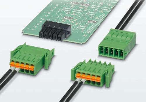
There are many different types of PCB connectors. Some have unique features, such as being press-fit and not requiring soldering, while others have filters that block EMI. Some have locking mechanisms to prevent inadvertent disconnections. Typically, we use straight pin header connectors when stacking parallel boards. However, depending on the application, you may choose any of these connectors.
In this article, we also discuss transfer signals and header receptacles and explain how each type of interconnection affects the transmission of signals. In addition, we discuss RCA connectors, Wire to Board PCB Connectors, and Surface Mount and Backplane connectors.
There are several types of PCB connectors, and a basic understanding of each is important for successful PCB integration. Orientation of the pins determines the polarity of each connector, and certain types of connectors can only make contact with specific connector types. The male and female PCB connectors are also sometimes referred to as “Pin Headers.” However, you should know that various other PCB connectors are available.
Printed Circuit Boards and Backplane Connectors
Printed Circuit Boards (PCBs) are the physical boards interconnecting electronic components. We make them from conductive copper strips attached to a non-conductive substrate. PCBs are the building blocks of many electronic components and systems, including computers and smartphones. When connected together, PCBs can form system host boards or single-board computers. Backplane connectors are an integral part of these systems, as they enable the coupling of PCBs.
The pin module 220 is a connector that contains a pair of signal conductors. These conductors each have a mating interface portion that resembles a pin, as well as contact tails that make electrical connections to vias on the printed circuit board. Both contact tails are press-fit-compatible, and the intermediate portions of each signal conductor become connected through the pin module 220.
Printed circuit boards and backplane connectors are two-piece devices that connect two or more printed circuit boards without needing a cable-to-board connection. A board-to-board connector is a high-performance product that mats two or more PCBs. TE engineers use sophisticated 3D tools to develop accurate board connectors.
We can use a printed circuit board as a backplane if it is attached to a conductive substrate. Backplanes help route signals between electrical connectors and provide reference planes for grounded conductors. The backplanes can consist of dielectric sheets stacked on top of one another. You can pattern some of these sheets with a conductive film on one or both surfaces.
PCB Connectors

PCB board connectors are one of the largest categories of connectors. They are designed to be mounted on or processed on a printed circuit board. There are two basic types of PCB connector orientations: board-to-board and wire-to-board. These types of connectors play a vital role in electrical devices and have various subcategories based on the purpose of the connector.
Several types of connectors for PCBs exist. The most common types of connectors terminate to holes in the board. In addition, there are through-hole and pressed-fit connectors. The choice of one connector depends on the design of the board and its use.
When choosing the right PCB connector, it is crucial to determine the system’s power capacity. High-power systems, for example, require more power. In these cases, the number of pins is less important. However, the reliability of the connector is more important. Therefore, it is vital to avoid connectors that will cause the board to overheat and potentially ignite plastic components. Shielded and EMI-protected PCB connectors are also available.
Wire to Board PCB Connectors
The main difference between wire-to-board and board-to-board PCB connectors is their shape. Wire-to-board connectors are made of copper, allowing for high-speed connections. On the other hand, board-to-board connectors consist of silicon or plastic. Copper cables are more flexible and can withstand high-speed reliable connection.
Wire to board PCB connector systems provide a simple, yet highly reliable, solution for routing power and signal between pc boards. The flexibility of these connectors makes them useful in a variety of industries. While wire to board PCB connectors were once associated with engineering complexities, today’s solutions are compact and designed to meet the demands of fast and automated surface mount assembly. In addition, wire-to-board PCB connectors offer long-term reliability and cost-effectiveness when used for transfer signals, header relays, or any other application.
Another type of wire-to-board PCB connector is the wafer type. This type of connector is polarized and has a better connection with PCB. One fixes the male connectors to the PCB, while we crimp female PCB connectors onto the wire. Wafer connectors are compatible with headers.
USB Connectors and the Different Connector Types
A USB connector is a component to connect a computer to a peripheral device. Its design simplifies the process of connecting gadgets via USB. A USB connector can be panel mounted, surface mounted, through-hole mounted, or cable mounted. USB On-The-Go standard supports some USB connectors, which allows some products to switch between host and device roles. Mobile phones, for instance, can act as a mass storage device, a USB reader, or both.
USB PCBs are characterized by a wide range of temperatures while in operation. They can function at extremes of temperature and even in the coldest conditions. Besides, they are capable of withstanding extreme electrical and mechanical forces. Using USB type PCBs in charging instruments and sound cards helps them perform better. We can also use such connectors in navigation devices, flexible electric circuits, and flash drives. A PCB containing a USB connector is a cost-effective, high-quality way to ensure your product is compatible with any USB device.
The USB family standard uses three connector types: a USB micro, a mini-USB, and a USB-C. We use the first two for mobile devices. USB data transfer supports five modes and five speeds. Unfortunately, each mode has different hardware requirements.
The B-type USB connector is the most common type of USB connector. Many electronics, including music players, use this type and is also the standard connector for power. The newest type of USB connector is the USB C, which can handle power, transmit data, and video at the same time.
Prototyping and Testing Connectors

While many PCB manufacturers offer various PCB connectors, they don’t create them equally. Fortunately, these connectors have a few key differences. Unlike Molex connectors, which you can only mat a few times, you can interconnect PCB connectors multiple times.
Choosing the right PCB connectors can help you achieve a variety of goals. The first thing to consider is the PCB’s overall purpose. Does the board need to provide power or communication to multiple devices? Should the connectors provide a signal or data? If you have to make changes frequently, you’ll need to choose connectors with different properties. For example, a connector designed for low current use wouldn’t be appropriate for high-power applications.
Another thing to consider is the cost per board. Again, your target market will help you determine your project’s best components and parts. It’s also important to include testing points and protocols in the design phase to identify potential manufacturing problems early. You can best control the cost per board when you know where to cut costs. Incorporating testing points and protocols during your project’s prototyping and testing phase can help you save money and ensure the highest quality product.
RCA Connectors
We use RCA Connectors to connect audio and video devices. They consist of three separate headers. RCA stands for Radio Corporation of America, and developed in the 1940s. Its initial use was to connect phonographs to amplifiers, but its popularity grew exponentially as the 1950s approached. Nowadays, it is a common type of connector for both audio and video transmissions.
Today’s technology uses RCA Connectors to carry all kinds of audio signals. Moreover, they are commonly color coded. Therefore, they are good audio connectors.
In electronic PCBs, RCAs serve as a bridge between two PCBs. One solders them parallel to the board surface and are generally 2.54mm in pitch. They have common use in breadboards and to connect jumper wires. XBee Chip Antennas and other electronic devices use a 2.0mm pitch version of RCA.
What do connectors provide?
These components are essential to the proper functioning of your electronic equipment. But they also collect dirt and corrode over time. To prevent power loss and maintain good contacts, you should clean your PCB connectors regularly. Cleaning them requires the right tools and techniques. For removing corrosion, you should use Isopropyl Alcohol. However, be careful when using this chemical, as it is flammable.
One type of PCB connector is the RITS connector. This type of PCB connector is color-coded to indicate its application and has a locking lever to facilitate mating. Other types of PCB connectors require the user to strip wires before mating them. We call some types of connectors parallel or mezzanine connectors, right angle connectors, and 180 degrees.
Edge to edge
What do edge to edge connectors provide to an external circuit? An edge connector is a set of pads and pins that allow the connection of external circuits and components. This connector typically has 25 strips, five of which can accommodate 4mm banana connectors/plugs or crocodile clips. The remaining three rings are for general-purpose input and output. Two of them connect to a micro-bit’s power supply.
When selecting a header connector, you should consider vertical and horizontal orientation. You can stack a vertical connector for maximum space efficiency, while you can keep a horizontal connector at low profile and allow for mating multiple PCBs. Depending on the application, you might want to consider the connectors’ different orientations (horizontal or vertical orientation).
Terminal Blocks & Board to Board PCB Headers
Terminal Blocks and PCB headers are integral parts of many electronic circuits. They allow reliable connections between two boards while offering mechanical strength. However, they are susceptible to corrosion due to salty air and wide temperature swings. Moreover, screw terminations can become unreliable when exposed to mechanical vibrations. In such situations, terminal blocks can be of great help to designers. However, you should know more about these components before buying them.
Terminal Blocks & Board to Body PCB Headers come in various designs to meet your needs. Pluggable versions of terminal blocks are convenient as they have no tools for installation and disassembly.
We make typical terminal blocks and PCB-to-Board PCB headers using metal, which can withstand high-voltage and high-current. Some have an integrated circuit to support their weight, while others are suitable for a single-layer board. There are also multi-level PCB headers available for high-current applications. When designing a PCB-to-Board PCB Header, you should consider the voltage and current requirements of the system and other design factors.
How to Power Multiple Electronic Devices With Single Power Connectivity
Single power connections are the most common way to run your household devices. But what can you do if you have more than one device? Here are a few ideas. First, consider what you’ll be using the single power connection for. You become amazed at how many devices you can connect to a single outlet. Then, choose one with two power strips and one USB port to transmit power. This way, you can power multiple devices without worrying about having to worry about which power strip is right for you.

