The DS1307 is a versatile and widely used Real-Time Clock Integrated Circuit (RTC IC) known for its accuracy and functionality. As a crucial component in various applications like data loggers, timekeeping, and scheduling systems, the DS1307 can be found in numerous electronic devices. This in-depth guide aims to provide insights into the pinout and functionality of the DS1307, making it easier for both beginners and experienced engineers to utilize it in their projects.
Understanding the DS1307 pinout is essential to ensure accurate timekeeping and seamless integration with microcontrollers, power supplies, and backup batteries. The DS1307 operates on a 5V power supply, includes a 32768 Hz crystal oscillator, and communicates via the I²C protocol, making it compatible with most microcontrollers. This compatibility enables easy integration into a variety of applications, ranging from simple digital clocks to complex home automation systems.
Along with addressing the pinout configuration, this guide will delve into the functionality of each pin, including power supply connections, I²C communication, and square wave output. By understanding the DS1307’s various features, users can harness the full potential of this Real-Time Clock IC and ensure the successful implementation of RTC capabilities in their projects.
DS1307 Pinout Overview
Pin Layout
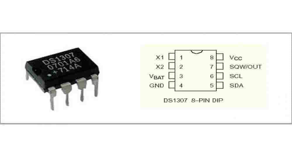
The DS1307 Real-Time Clock IC consists of 8 pins which are essential for various functionalities. Here is a brief description of each pin:
- VCC (Pin 1): Power supply voltage (5V or 3.3V).
- GND (Pin 2): Ground reference.
- CLK (Pin 3): Serial clock input for I2C communication.
- DATA (Pin 4): Serial data input/output for I2C communication.
- SQW (Pin 5): Square wave output or interrupt output.
- OSC1 (Pin 6): Oscillator input, connects to a crystal.
- OSC2 (Pin 7): Oscillator output, connects to a crystal.
- NC (Pin 8): No connection. This pin is not used in the DS1307 functioning.
Power Supply Pins
The DS1307 requires an external power supply for proper functioning. The power supply pins are as follows:
- VCC (Pin 1): Provides the operating voltage to the IC. It can be either 5V or 3.3V.
- GND (Pin 2): Serves as the ground reference for the IC.
I2C Communication Pins
The DS1307 uses I2C protocol for communication with other devices. There are two primary pins for I2C communication:
- CLK (Pin 3): The serial clock input pin is responsible for synchronizing data transfer.
- DATA (Pin 4): The serial data input/output pin transmits and receives data.
Oscillator Pins
The oscillator circuit in the DS1307 requires an external 32.768 kHz crystal for accurate timekeeping. The pins associated with the oscillator are:
- OSC1 (Pin 6): The oscillator input connects to one leg of the crystal.
- OSC2 (Pin 7): The oscillator output connects to the other leg of the crystal.
Square Wave Output Pin
The DS1307 has a square wave or interrupt output pin that can generate a periodic signal or serve as an external interrupt source:
- SQW (Pin 5): This pin outputs square wave frequencies or an interrupt signal, depending on the configuration.
Functional Description of DS1307 Pins
The DS1307 Real-Time Clock IC is a widely used integrated circuit that keeps track of time even when the main system’s power is turned off. Understanding the pinout and their functions are crucial for incorporating this IC into a circuit. In this section, let’s take a look at the functions of the DS1307 pins.
-
V_CC (Pin 1): This pin is the power supply for the DS1307. A supply voltage ranging from 4.5V to 5.5V is required for proper operation of the IC.
-
GND (Pin 2): This pin serves as the ground (0V) connection for the DS1307. It needs to be connected to the circuit ground to establish a common reference point.
-
SDA (Pin 3): The Serial Data (SDA) pin is a bidirectional data pin used for data transfer between the DS1307 and a microcontroller. It uses the I2C communication protocol to transmit and receive data.
-
SCL (Pin 4): The Serial Clock (SCL) pin is used to provide the clock signal necessary for I2C communication between the DS1307 and a microcontroller.
-
SQW/OUT (Pin 5): This multi-purpose pin can be configured as either an output for a square wave or a general-purpose output. The frequency of the square wave signal can be selected from a range of options (1Hz, 4096Hz, 8192Hz, or 32768Hz).
-
32K (Pin 6): This is an optional pin providing a 32.768kHz output signal, often used as a clock signal for other devices or as a reference for the main system.
-
V_BAT (Pin 7): The battery input pin is crucial for the DS1307 to maintain accurate timekeeping when the main power supply is disconnected. It should be connected to a battery with a voltage of 3V.
The DS1307 has eight pins, with the eighth pin not being connected or used. The pin descriptions are summarized in the table below:
| Pin Number | Pin Name | Function |
|---|---|---|
| 1 | V_CC | Power supply input |
| 2 | GND | Ground connection |
| 3 | SDA | Serial Data for I2C communication |
| 4 | SCL | Serial Clock for I2C communication |
| 5 | SQW/OUT | Configurable square wave or general output |
| 6 | 32K | 32.768kHz output signal |
| 7 | V_BAT | Battery input for timekeeping |
| 8 | NC | Not connected |
By understanding the functions of these pins, you will be well-equipped to integrate the DS1307 Real-Time Clock IC into your projects and ensure accurate timekeeping even when your system is powered down.
How the DS1307 Real-Time Clock Works

Timekeeping Operation
The DS1307 operates using a 32.768 kHz crystal oscillator, which serves as a reliable timekeeping source. This low-frequency crystal ensures precise timekeeping with minimal power consumption. Once the oscillator is running and the device is powered, the DS1307 maintains the current time and date information.
Clock and Calendar
The DS1307 Real-Time Clock includes a calendar function, which takes into account months, days, weekdays, and leap years. It can provide time information in a 12-hour or 24-hour format. Its internal registers store seconds, minutes, hours, day of the week, date, month, and year with automatic leap year compensation up to the year 2100.
I2C Interface
The DS1307 communicates with microcontrollers using the I2C (Inter-Integrated Circuit) protocol. The I2C lines are:
- SDA (Serial Data Line): Bidirectional data line for transmitting and receiving data
- SCL (Serial Clock Line): Clock input that synchronizes data transfer
The I2C interface allows for easy connection to microcontrollers and other I2C-compatible devices, making it a popular choice for timekeeping applications in embedded systems.
RAM Access
The DS1307 RTC also includes 56 Bytes of battery-backed, non-volatile RAM. This RAM can be accessed through the I2C interface the same way as the clock registers. This memory can be used to store small amounts of data that need to persist even when the main power supply is removed, making it suitable for storing settings or other critical information.
Applications of DS1307
The DS1307 real-time clock IC is widely used in various applications due to its accurate timekeeping and low power consumption. Some of the common applications include:
-
Embedded systems: DS1307 is commonly used in microcontroller-based systems to provide accurate timekeeping and date tracking. This helps in the scheduling and management of crucial tasks, ensuring efficient and reliable performance.
-
Data loggers: These devices record data periodically and often require a precise time stamp for each data point. DS1307 serves as an ideal choice, providing accurate timekeeping and easy integration with most microcontroller units (MCUs).
-
Industrial automation: Time-sensitive processes and operations in industrial settings need accurate time-tracking. DS1307 ensures precise control and coordination of production lines, machine tools, and automation equipment.
-
Consumer electronics: Devices such as digital clocks, smartphones, and home automation systems demand accurate timekeeping to ensure smooth functioning. The DS1307 provides the necessary precision while minimizing power consumption.
-
IoT devices: In Internet of Things (IoT) systems, devices often need to synchronize their clocks. The DS1307 stands out with its low power consumption and ease of integration, making it a popular choice for IoT projects.
In summary, the DS1307 real-time clock IC offers a reliable and low-power solution for accurate timekeeping in a wide range of applications. Its ease of integration with MCUs and minimal power requirements make it a valuable component in various industries.
DS1307 Interfacing with Microcontrollers
The DS1307 is a popular real-time clock (RTC) integrated circuit (IC) that can be easily interfaced with microcontrollers such as Arduino and Raspberry Pi. This section will show you how to connect the DS1307 to these microcontrollers and provide example codes for reading and setting the time.
Arduino Example
To connect the DS1307 RTC IC with an Arduino microcontroller, you will need to use the I2C communication protocol. Here are the steps to interface the DS1307 with Arduino:
- Connect the DS1307 VCC pin to the 5V power supply of the Arduino.
- Connect the GND pin to the ground of your Arduino.
- Connect the SDA pin of the DS1307 to the A4 pin (SDA) of the Arduino.
- Connect the SCL pin of the DS1307 to the A5 pin (SCL) of the Arduino.
Here is a simple Arduino code example that reads the time from the DS1307 and displays it on the Serial Monitor:
#include <Wire.h>
#include "RTClib.h"

RTC_DS1307 rtc;

void setup() {
  Serial.begin(9600);
  rtc.begin();
}

void loop() {
  DateTime now = rtc.now();
  Serial.print(now.hour(), DEC);
  Serial.print(':');
  Serial.print(now.minute(), DEC);
  Serial.print(':');
  Serial.println(now.second(), DEC);
  delay(1000);
}
Raspberry Pi Example
To interface the DS1307 with a Raspberry Pi, you will also use the I2C communication protocol. Follow these steps to connect the DS1307 to a Raspberry Pi:
- Connect the DS1307 VCC pin to the 5V power supply pin of the Raspberry Pi (pin 2 or 4).
- Connect the GND pin to the ground pin of your Raspberry Pi (pin 6).
- Connect the SDA pin of the DS1307 to the SDA pin of the Raspberry Pi (GPIO2, pin 3).
- Connect the SCL pin of the DS1307 to the SCL pin of the Raspberry Pi (GPIO3, pin 5).
Here’s a Python code example that reads the time from the DS1307 and prints it to the console:
import smbus
import time

DS1307_ADDRESS = 0x68

def bcdToDec(value):
    return ((value//16) * 10) + (value % 16)

bus = smbus.SMBus(1)

while True:
    bus.write_byte(DS1307_ADDRESS, 0)
    raw_data = bus.read_i2c_block_data(DS1307_ADDRESS, 0, 7)
    second = bcdToDec(raw_data[0])
    minute = bcdToDec(raw_data[1])
    hour = bcdToDec(raw_data[2] & 0x3F)
    print(f"{hour:02d}:{minute:02d}:{second:02d}")
    time.sleep(1)
Both examples demonstrate how to read the current time from the DS1307 RTC using the I2C communication protocol. By following the steps provided and utilizing the example code, you will be able to interface the DS1307 Real-Time Clock IC with an Arduino or Raspberry Pi microcontroller successfully.
DS1307 Power Solutions and Battery Back-Up
The DS1307 Real-Time Clock IC requires a power supply to function effectively. This section aims to discuss various power solutions and battery back-up options to ensure the DS1307 runs as intended.
The primary power source for the DS1307 is typically a 5V supply that may come from either a battery or a regulated power supply. Ideally, a voltage regulator should be used to ensure a steady 5V input, preventing fluctuations that might affect the clock’s performance.
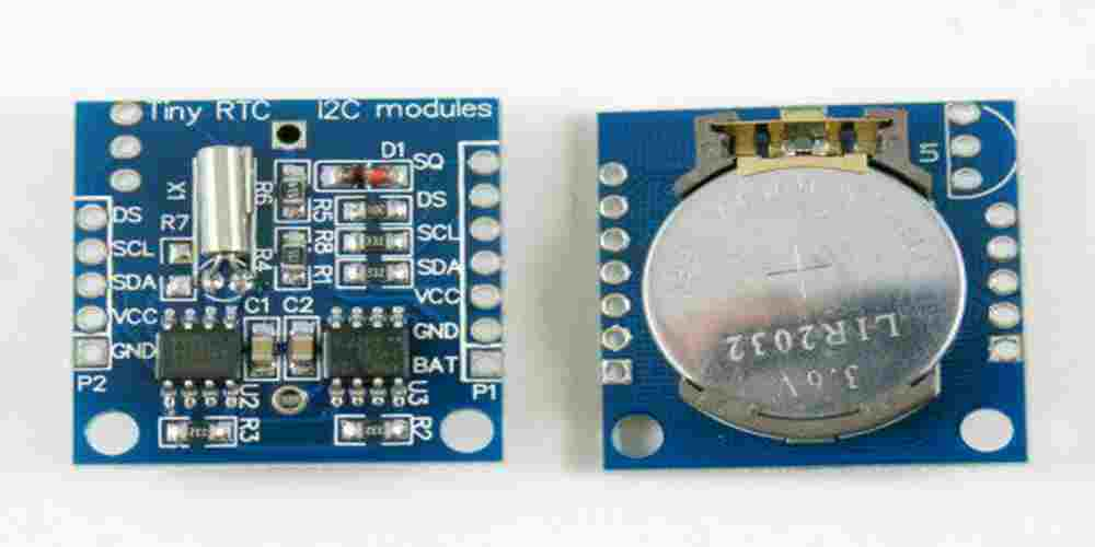
Coin Cell Battery Back-Up
A notable feature of the DS1307 is its ability to handle battery back-up. This back-up ensures that the device continues to maintain accurate timekeeping even during power outages.
- Battery Type: A commonly used battery type for back-up is the CR2032 3V coin cell, which is inexpensive and widely available.
- Battery Voltage Range: The allowable battery voltage range for the DS1307 is between 2V and 3.5V.
- Battery Pin Connection: The battery should be connected to the VBAT (Pin 3) and GND (Pin 4).
The DS1307 automatically switches between the primary power source and the battery backup, ensuring uninterrupted operation.
Power and Battery Current Consumption
Understanding the current consumption of the DS1307 is crucial for determining the overall efficiency and battery life. Here are some important figures to consider:
- Supply Current: When operating from a 5V power source, the DS1307 typically consumes around 200µA of current.
- Standby Current: A coin cell battery will contribute approximately 3µA of standby current to the DS1307.
Consider these values while choosing power supplies and batteries to ensure optimal performance and prolonged battery life in case of primary source failure.
Summary
Providing reliable power and battery back-up solutions to the DS1307 Real-Time Clock IC is essential for maintaining accurate timekeeping. With proper implementation, the DS1307 will continue to function even during power outages, ensuring dependable operation.
Troubleshooting Techniques
When working with the DS1307 Real-Time Clock IC, it’s common to encounter issues or challenges. Here are a few troubleshooting techniques to resolve them efficiently.
-
Power Supply Issues: Ensure the IC has the correct voltage supply of 5V. Check for any loose connections, and confirm that the IC’s VCC pin is connected to the appropriate voltage supply.
-
I²C Communication: Check for a proper SDA (data line) and SCL (clock line) connection to the microcontroller. Ensure that the pull-up resistors are connected to both the SDA and SCL lines, and verify their values (usually 4.7K or 10K Ohms).
-
Timekeeping Accuracy: The DS1307 uses an external 32.768 kHz crystal oscillator for timekeeping. Make sure the oscillator is connected to the correct pins (X1 and X2) and that it is functioning properly. The capacitor values (typically 6pF or 12.5pF) attached to the crystal determine the crystal’s stability and accuracy; refer to the DS1307 datasheet and the crystal’s datasheet for guidance.
-
Battery Backup: Whenever the system experiences power loss, the DS1307’s SQW/OUT pin should be connected to a recommended battery (such as a CR2032 3V lithium coin cell) to maintain timekeeping. Double-check battery connections and confirm the battery isn’t depleted.
-
Address Conflicts: Avoid I²C address conflicts by ensuring that no other devices on the same bus share the same address (0x68) as the DS1307.
-
Initialization: Make sure the CH (clock halt) bit in the seconds register is set to zero, allowing the clock to run. Additionally, verify that other control bits, such as the frequency selection bits for the SQW/OUT pin, are configured to your desired settings.
These troubleshooting techniques should help resolve common issues encountered when working with the DS1307 Real-Time Clock IC. Remember to also consult the DS1307 datasheet for additional guidance and specifications.
Conclusion
In this guide, we have explored the DS1307 pinout and its various features that make it a popular choice for real-time clock applications. The DS1307 offers a simple interface to track time and date, with easy integration to various microcontrollers using I²C communication protocol.
The key features of the DS1307 that we have discussed include:
- 7 pins for I²C communication, power supply, and auxiliary functions
- Integration of 32.768 kHz crystal oscillator for accurate timekeeping
- Battery backup for maintaining time and date data during power loss
- Programmable square wave output for additional functionality
It is important to follow proper connectivity guidelines and consider factors such as the crystal oscillator load capacitance, as well as appropriate battery selection for optimal performance. Overall, the DS1307 provides a reliable solution for real-time clock requirements in a range of applications, making it an invaluable component in the world of electronics.
