Electrical testing forms a significant aspect of any circuitry design. It arises because both electrical and electronic circuits have a common denominator – current. Current powers the whole circuit and ensures each component executes functions as anticipated in the design. Most circuit board engineers and designers have to consider different electrical elements when designing various circuitry forms.
If you want to design and develop a top-tier electronic or electrical circuit board, it is necessary to ensure that it meets all the quality standards. So what does electrical testing involve when it comes to electronic and electric circuits? What is its importance, and what types of electrical testers should you know about? This article will canvass all the major areas you need to know about electrical testing.
Electrical Testing in the Context of Circuit Boards
Like how electricians check for a range of electrical functions in commercial and residential electrical wiring, circuit boards also undergo this process. However, the type and manner slightly differ. Nonetheless, the endgame often proves similar – to ensure the integrity and proper functioning of the circuitry.
The concept and reality of printed circuit boards have had a steady rise through the years. It has resulted due to its significance to electronic and electrical equipment and devices. As the PCB and other electronic and electrical circuits continued evolving, the focus has centered on enhancement. It has featured aspects such as incorporating more layers, more components, blind vias, buried vias, decreasing circuit widths, and controlling impedance, among other elements.
The industry has pushed the limits regarding materials and equipment used in the fabrication of circuit boards. What’s more? The focus on tweaking the processes to enhance yield and revel in the successes has detracted from a fundamental aspect of testing electrical circuits. But increasing the complexity of the circuitry implies increased risk in electrical failures, which further impact the lead times. However, the emergence of technology and the subsequent reliance by manufacturers shortens these lead times.
Forms of Electrical Testing in Printed Circuit Boards
Different electronic or electrical bare circuit board manufacturers have divergent ways of testing circuitry. For instance, RayMing PCB and Assembly deploy several electrical tests, including the flying probe test. However, most testing procedures focus on the following vital aspects regardless of the electrical testing method deployed.
For the Bare Board
The testing of the bare board often entails using resistance and capacitance tests, mostly in combination. Capacitance testing entails short and open tests by charging a plane or net before probing every net to gauge the capacity induced. However, it is a method that accrues a lot of inaccuracies due to the inherent inconsistency when it comes to fabricating or producing electrical or electronic circuit boards. It is also instrumental in remembering that field-effect shorts testing utilizes a similar technique.
For Resistance
It measures the available resistance in the net. By principle, any electric flow in a conductor causes atoms and electrons to collide, impacting the electron flow. Such an occurrence gets referred to as resistance. As a result, most decent conductors need to have low resistance. A conductor’s resistance, however, depends on the cross-sectional area and length of the conductor.
Electrical Testing Processes in Circuit Boards
The Circuit board production process often proves lengthy. However, one of the crucial steps at the tail end entails electrical testing, which ensures the completeness of the interconnectivity of the circuit board. A lot of PCB production houses use different testing methods, though some are common across the industry. So what are the typical electrical testing processes most PCB houses conduct on circuit boards?
In-Circuit Testing
It is an incredible electrical testing approach for circuits, though it transcends electrical tests alone. While in-circuit testing is a potent tool for printed circuit board testing, it deploys the use of a bed of nails to access and test circuit nodes besides checking their corresponding performance. It also tests specific functional aspects of digital circuits. However, the complexity of the process can transform it into an economically prohibitive venture.
In-circuit testing applies perfectly for testing high-volume and advanced products. But compared to the flying probe testing, aspects like development lead times besides up-front costs are longer and higher, respectively. It results from the contract manufacturer explicitly creating a distinct ICT fixture for every printed circuit board.
A major benefit from in-circuit testing is the reduced costs for every unit once the ICT tool becomes operational. Compared to the flying probe testing, the in-circuit testing takes around one minute per test cycle. Flying probe testing takes about fifteen minutes for each board.
Benefits
- It is faster compared to the flying probe test per printed circuit board unit.
- The process costs less for every unit compared to the flying probe test (FPT)
- It checks for opens, shorts, resistance, component tolerance, and capacitance.
- In-circuit testing targets components individually
- The process also tests and ascertains the logic functionality
- It can execute on-board verification of FPGAs
- using a pressure inspection or test; in-circuit testing can check the BTC component’s integrity, especially on their soldering.
Weaknesses
In-circuit testing has prolonged development lead times
It requires custom tooling and programming to ensure success
It features high up-front fees or costs
In-circuit testing fails to test non-electrical components or connectors
The process of in-circuit testing cannot work on components that work as a unit or together
Flying Probe
It is a method of testing circuit boards using a small number of fixed and mobile probes to make simultaneous in-circuit testing on the printed circuit board’s bottom and top layers. It comprises high-precision needles with varied needle quantities based on the machine. Some have as few as four needles, whereas others can utilize up to twenty needles for each printed circuit board side. The machine is programmed to contact the parts or component pins besides performing functional and electrical tests. Such tests determine how to fit a board proves for deployment in its respective application area.
The flying probe test is ideal for electronic products in the initial stages of the development or low-volume product orders. The process needs no specific or custom tooling as customization happens through a programmed or automated process (it uses the CAD details provided to the EMS). The process exhibits higher costs per unit compared to ICT as a result of the lengthy test cycle.
Benefits
- No custom requirement for custom tooling
- The programming process needs less time
- It checks for resistance, opens, capacitance, shorts, and component or parts tolerance.
- It is capable of testing LED
- The process exhibits low initial or upfront costs
- The approach can perform on-board verification of FPGAs
Drawbacks
- Cycle test times prove higher besides higher cost-per-unit costs
- It fails to test non-active components or connectors
- It also fails to test parts or components that operate together
Further, the type of electrical test conducted has to meet the international and acceptable industry-related testing standards. But what types of electrical testers apply in the context of circuits?
Electrical Tester Types and their Corresponding Uses
Electric testers are fundamental tools most electronic and electric circuit manufacturing companies use in testing circuit boards. The same instruments also come in handy for electricians when testing different aspects of electrical wirings or circuits. While some testers prove multi-functional regarding performing almost every electrical testing activity, others prove adept at singular functions.
Most electrical testers get deployed in checking for voltage levels (both in DC and AC circuits), amperage, short circuits, continuity, polarity, etc. So why can we now not get into the thick of things and canvass some of them?
Non-Contact Voltage Testers
It also gets inferred as the inductance tester. The tester has a reputation as one of the safest testers besides proving simple to use. A non-contact voltage tester allows for voltage checking within the circuitry (traces or wires) without any need for touching the parts. It comes as a mini-wand complete with a tiny tip for sensing purposes. Additionally, it detects voltage in electrical wiring, circuit breakers, outlets, light sockets, switches, lamp cords, etc. It provides a prompt reading of the voltage when stuck (the tip) to an electricity-conducting cable or trace.
In most cases, inductance testers utilize a battery in powering the device. However, most models will provide the voltage information by lighting up red and producing a buzzing sound. Such inductance testers come equipped with pocket clips, making them simple to carry around. A simple non-contact voltage tester will only determine the presence or absence of voltage, while the advanced and complex ones offer an elementary voltage measurement present within a circuit. However, such measurements cannot compare to the precision realized when using a multi-meter or other tester types.
Since the device or tester comes battery-operated, it is prudent to have the battery fully charged to ensure optimal functionality of the inductance tester whenever applicable. To ensure the tester works, use a live switch or outlet to verify it. One of the main drawbacks of this inductance tester encompasses its inability to test multiple functions.
Neon Voltage Testers
It also gets referred to as neon circuit testers. This tester type comes simplified with a decent small cross-section equipped with a neon bulb or light inside. It also has two short lead wires with a metal probe on either end. Further, Neon circuit testers demonstrate or show the presence or absence of voltage in a circuit. However, the voltage tester does not measure the amount of voltage present. It also differs from a non-contact voltage tester as it requires contact with the circuitry or circuit wires, outlet slots, screw terminals (using the probes). Additionally, it functions without a battery, and this makes it reliable as an electrical testing tool.
As a circuit tester, the neon voltage tester requires you to touch one end of the tester probe to a hot screw terminal, outlet slot, or wire, with the other probe touching the ground or a neutral. In the presence of voltage or current, the neon bulb lights up. It is also an instrumental tester in determining how proper an outlet is grounded. For instance, it implies a faulty outlet grounding whenever inconsistencies exist. It primarily occurs where the voltage tester lights when the probes get inserted correctly to the respective neutral slots and hot slots but fail when the probe gets shifted to the grounding slot.
Important Notes
While it is a simple tool to deploy, it needs extreme care when it comes to handling. If you touch by accident either of the probes while testing a circuit with voltage, you will get shocked. Therefore, it is instrumental in using plastic casings when handling the neon probe in a test process.
The voltage tester is also inexpensive by not using a battery and thus can get relied upon whenever the non-contact tester fails. The tester also provides an incredible way of ascertaining that your non-contact tester still proves operational.
Plug-In Circuit Analysers
The relatively inexpensive and simple-to-use tester offers a lot of information concerning an electrical circuit when plugged into its outlet. It comes in a design that enables it to test electrical outlets, including the ordinary ones, provided they possess three slots. The plug-in circuit analyzer cannot test the older two-slot electrical outlets because of the absence of ground. For such circuits, it becomes better to have them tested using the neon circuit tester.
PCAs or Plug-in circuit analyzers contain a triple neon set of lights that come on in distinctive patterns to illustrate particular test results. Additionally, the enclosed chart sticker assists in the interpretation of the diverse light patterns. Distinct light patterns can imply a correctly wired outlet, an open circuit, a reverse-wired outlet, or the status (presence or absence) of a ground connection.
Circuit analyzers function without a battery, making them convenient as all you have to do entails plugging them into the outlet. However, the outlet getting tested needs to have power for the tester to function.
The plug-in circuit tester is affordable, and this becomes useful for homeowners interested in electrical work (DIY).
Continuity Tester
Continuity testers are electric tester devices that run on battery power. It contains a probe on one end and another probe or an alligator on the other end, all connected by a cord. Whenever you touch both probes/ends together, the circuit completes, and light comes on. It is an excellent tester option for checking aspects like the functioning of single-pole switches.
Unlike other tester types, a continuity tester gets deployed on unpowered circuits or disconnected devices or wiring from the circuit. Turning off the power source is pivotal if the device tested for continuity is attached to a circuit wiring. Using a continuity tester can become dangerous on voltage-carrying wiring.
Most users, for this reason, deploy continuity testers on devices that get entirely disconnected from the circuitry. For instance, a continuity tester provides a decent way of checking how intact a lamp wiring proves. It can also check the lamp’s inner mechanism on aspects like the functioning of a disconnected switch.
In the absence of current flowing through the circuit, a continuity tester can also become helpful in checking wire runs and ensuring the completeness of the circuit. It identifies short circuits within specific wiring. What’s more? The tester proves inexpensive and capable of checking and testing the electrical condition of a circuit. However, it is unlikely to find it with most DIY users.
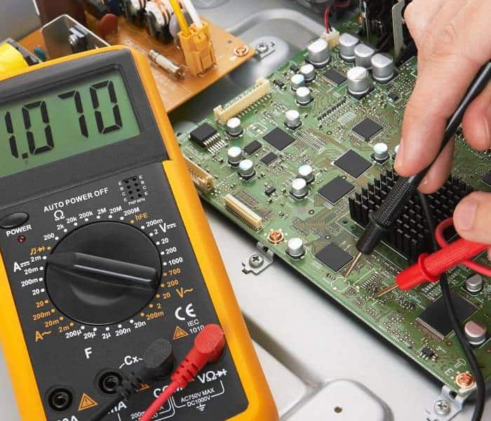
Multi-meter
A multi-meter proves the most robust when it comes to the different types of electric testers. It is capable of diverse types of testing functions. You are likely to find most electrical experts using this tool as it gives accurate readings. It measures and tests capacitance, DC and AC, continuity, voltage, and frequency. Understanding how to operate and deploy all the functions become integral in getting all the relevant electrical details about circuits.
Multi-meters come enclosed in box bodies that have analog and digital readouts. It also possesses a dial instrumental in setting tests functions. Other vital attributes within the box build include two long leads complete with metallic probe ends. However, the accuracy and quality of multi-meters vary based on the brand. It is, therefore, crucial to buy a high-quality multi-meter when you need one.
A multi-meter can do numerous functions. However, such a multifaceted instrument needs plenty of time to master the different testing functions available.
Solenoid Voltage Tester
It is a type of tester commonly referred to by the nickname “wiggies.” A solenoid voltage tester comes as a multi-function electric tester. However, they prove simpler and easier to use compared to the battery-run multi-meter counterpart. It can come in either digital or analog models. The testers can test polarity and voltage.
Most users deploy solenoid voltage testers to determine or test DC and AC voltages within the 100-600V range. However, most experts prefer the SVT over the multi-meter because of its rugged nature and absence of batteries. But it indeed lacks the accuracy exhibited by the multi-meter, especially on giving the voltage value in terms of numerical measurement.
Solenoid voltage testers have two probes attached to wires extending from the tester bottom. The absence of battery reliance makes them ready for use in checking voltage. It also has a vibrating or clicking mechanism installed, primarily when the tester detects some voltage. The extent of vibration or clicking corresponds to the amount of voltage detected. Additionally, it has low impedance and thus will trip circuit breakers or the GFCI (ground-fault circuit interrupter) devices during testing operations.
While the general public often lacks familiarity with the existence of solenoid voltage tester, it comes relatively cheap (almost half the price of multi-meters). Additionally, finding it in a big-box retailer can prove futile. You will likely get it at your online retailer of choice or electrical supply provider.
Digital Clamp Meter
The tool is synonymous with most professional electricians. A digital clamp meter combines the functions of a current sensor and a multi-meter. It is also slightly costlier than its multi-meter counterpart. Plenty of subtle differences exist between the functions of a clamp meter and a multi-meter. However, the most apparent feature includes the clamping jaws, which are instrumental in gripping wire conductors. It makes it safer and simpler to use some dangerous applications. For instance, when working on testing circuits in a panel of an open circuit breaker. The digital clamp meter also possesses wire leads, which allows for utilizing the tool as a typical multi-meter.
A digital clamp meter comes as an electrical specialty tool and is thus not common among many users. While practically similar to the functionality of a multi-meter, it offers an operationally sound mode practical for most electrical professionals.
Wand Voltage Meter
It comes as another specialty tester type. The wand voltage meter primarily applies to electrical experts. It functions in two distinct ways, though it primarily tests voltage numerically. One of the key ways it functions includes the presence of wire leads (which prove similar to those in multi-meters or neon voltage testers) that measure continuity or voltage by touching them to metal contacts or bare wires. The second way is through the presence of electrostatic wands, which detect and quantify voltage by holding the wands close to the metal contacts or wires. For instance, placing the electrostatic rods near NM cables will detail the total voltage getting carried by the cable.
It is prudent to note that a wand meter proves relatively expensive compared to its other tester counterparts. Additionally, it is a potent tool for electrical experts and must have in their toolbox.
Final Thoughts
Circuits are essential for every electrical and electronic product. However, to end up with functional circuitry, electrical testing becomes key. It not only guarantees the circuitry’s integrity but also averts damages to the electronic or electrical device. Therefore, as a circuitry enthusiast, understanding some of the electrical testers pivotal in circuit development becomes non-negotiable. If you have read this piece, we hope you now understand the various tools you can use for electrical testing (both for printed circuit boards and electrical circuits).
