Fusion 360 is a popular computer-aided design (CAD) software that is widely used for electronics design. It is a powerful tool that allows users to create 3D models and simulate the behavior of electronic circuits in real-time. Fusion 360 is designed to be user-friendly, with a simple and intuitive interface that makes it easy for beginners to get started.
One of the key features of Fusion 360 is its ability to integrate electronics design with mechanical design. This means that users can design both the mechanical and electronic components of a product in the same software, saving time and reducing errors. Fusion 360 also includes a range of tools for designing printed circuit boards (PCBs), including schematic capture, PCB layout, and routing.
Overall, Fusion 360 is an excellent choice for electronics design, offering a range of powerful tools and a user-friendly interface. Whether you are a professional electronics designer or a hobbyist, Fusion 360 can help you bring your ideas to life. With its integrated approach to electronics and mechanical design, it is a versatile and flexible tool that can be used for a wide range of projects.
Getting Started with Fusion 360 Electronics Design
Creating a New Electronics Design Project
To get started with Fusion 360 Electronics Design, you’ll need to create a new project. To do this, open the Fusion 360 software and select “New Electronics Design Project” from the “File” menu. This will create a new project with a default schematic and layout view.
Navigating the Fusion 360 Electronics Design Workspace
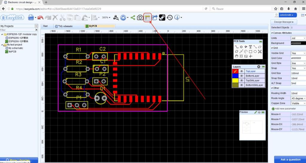
Once you’ve created your project, you’ll be presented with the Fusion 360 Electronics Design workspace. This workspace is divided into several sections, including the schematic editor, layout editor, and library browser. You can switch between these sections using the tabs at the bottom of the workspace.
Adding Components to Your Design
To add components to your design, open the library browser and select the components you want to use. You can then drag and drop these components onto the schematic editor. Once you’ve added your components, you can connect them using wires and nets.
Connecting Components with Wires and Nets
To connect components with wires and nets, select the “Wire” tool from the toolbar and click on the pins you want to connect. You can then drag the wire to the other pin and click again to complete the connection. Nets work in a similar way, but allow you to connect multiple pins together.
That’s it! With these basics, you’re ready to start designing your own electronic circuits using Fusion 360 Electronics Design.
Customizing Your Electronics Design

Creating Custom Components
One of the most powerful features of Fusion 360 Electronics is the ability to create custom components. This allows you to design unique electronic circuits that fit your specific needs. To create a custom component, you can use the built-in component editor in Fusion 360 Electronics.
To create a custom component, you will need to define its schematic symbol and footprint. The schematic symbol is the graphical representation of the component in the schematic, while the footprint is the physical layout of the component on the PCB. Once you have defined your custom component, you can add it to your library and use it in your designs.
Defining Custom Footprints
When designing a custom component, it is important to define its footprint accurately. The footprint defines the physical layout of the component on the PCB, and incorrect footprints can cause problems during assembly or cause the component to fail.
Fusion 360 Electronics includes a powerful footprint editor that allows you to create custom footprints for your components. You can define the shape, size, and orientation of the pads, as well as the placement of the component’s body.
Creating Custom Libraries
To make it easy to reuse your custom components, you can create custom libraries in Fusion 360 Electronics. A library is a collection of components that can be easily accessed and added to your designs.
To create a custom library, you can use the built-in library editor in Fusion 360 Electronics. You can add your custom components to the library, along with any other components that you frequently use in your designs. Once you have created your library, you can easily access it from within Fusion 360 Electronics and add components to your designs with just a few clicks.
Overall, the ability to customize your electronics design is a powerful feature of Fusion 360 Electronics. By creating custom components, defining custom footprints, and creating custom libraries, you can design electronic circuits that are tailored to your specific needs.
Simulating and Analyzing Your Electronics Design
Fusion 360 offers a comprehensive set of tools for simulating and analyzing your electronics design. With these tools, you can identify potential issues and optimize your design before you start building it.
Running Circuit Simulations
Fusion 360’s circuit simulation tool allows you to simulate and test your circuit design before building it. You can use this tool to verify the behavior of your circuit and identify any potential issues. You can also use it to optimize your design by experimenting with different component values and configurations.
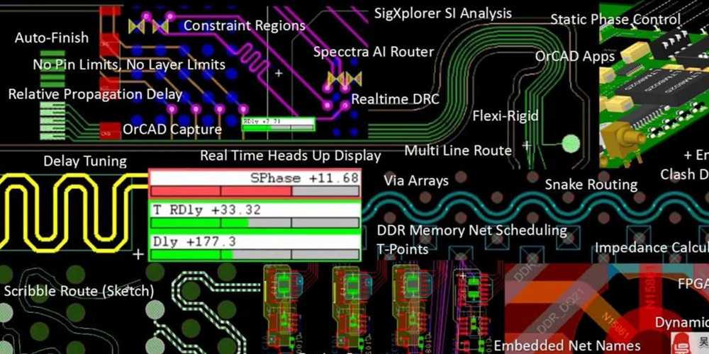
Analyzing Signal Integrity and Power Integrity
Fusion 360’s signal and power integrity analysis tools allow you to analyze the behavior of your circuit in more detail. These tools can help you identify potential issues with signal quality, power delivery, and noise. You can use this information to optimize your design and ensure that it performs as intended.
Performing Thermal Analysis
Fusion 360’s thermal analysis tools allow you to simulate the temperature distribution in your electronics design. You can use this tool to identify potential hot spots and optimize your design for better cooling. This can help ensure that your design operates reliably and efficiently.
In summary, Fusion 360’s simulation and analysis tools provide a powerful set of features for electronics designers. By using these tools, you can identify potential issues and optimize your design before you start building it.
Collaborating and Sharing Your Electronics Design
Collaborating with Team Members on a Design
Fusion 360 allows you to collaborate with team members on your electronics design in real-time. You can invite team members to your project, assign roles and permissions, and work together on the same design. This feature can enhance your productivity and help you to complete your project faster.
The collaboration tools in Fusion 360 also allow team members to leave comments, make edits, and suggest changes to the design. This helps to ensure that everyone is on the same page and that the design meets the requirements of all team members.
Exporting Your Design for Manufacturing
Once you have completed your electronics design, you can export it in various file formats for manufacturing. Fusion 360 supports a wide range of file formats, including DXF, DWG, and STEP. This makes it easy to export your design to the manufacturing software of your choice.
Exporting your design for manufacturing also allows you to check for any errors or issues that may arise during the manufacturing process. This can save you time and money by identifying potential problems before they occur.
Sharing Your Design with the Fusion 360 Community
Fusion 360 also allows you to share your electronics design with the Fusion 360 community. This can be a great way to get feedback on your design, learn from other designers, and showcase your work.
When you share your design with the Fusion 360 community, you can also access a wide range of resources, including tutorials, forums, and user groups. This can help you to stay up-to-date on the latest developments in electronics design and connect with other designers who share your interests.
In summary, collaborating and sharing your electronics design in Fusion 360 is easy and efficient. With the collaboration tools, exporting options, and community resources available, you can work with your team members, export your design for manufacturing, and share your work with the world.
