Printed Circuit Board (PCB) preamp mic layout is an essential aspect of the audio recording process. A preamp is a device that amplifies a microphone’s signal before it is sent to the recording equipment. The PCB preamp mic layout determines how the preamp components are arranged on the PCB.
The layout of the preamp mic PCB is critical because it can affect the quality of the audio signal. A poorly designed layout can introduce noise and interference into the signal, reducing the audio quality. On the other hand, a well-designed layout can minimize noise and maximize the signal-to-noise ratio, resulting in high-quality audio recordings. PCB preamp mic layout is, therefore, an important consideration for audio engineers and designers.
In this article, we will explore the basics of PCB preamp mic layout, including its importance, the key components, and best practices for designing a high-quality layout. We will also discuss some common mistakes to avoid when designing a PCB preamp mic layout. By the end of this article, you will have a better understanding of how to design a high-quality PCB preamp mic layout for your audio recording projects.
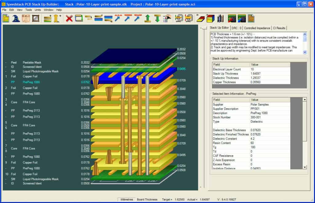
PCB Layout
When designing a PCB preamp mic, the layout of the board is crucial to ensure the circuit functions correctly. This section will cover the design considerations, component placement, and routing for a successful PCB layout.
Design Considerations
Before starting the PCB layout, it’s important to consider the design specifications and requirements. The preamp mic circuit should be optimized for low noise, high gain, and high input impedance. The PCB layout should also take into account the physical space available for the board and the desired input and output connectors.
Component Placement
The placement of components on the PCB is important for minimizing noise and interference. High impedance components should be placed close to the input connector, while low impedance components should be placed near the output connector. Power supply components should be placed as far away from the input and output as possible to avoid noise coupling.
Table 1: Component Placement Guidelines
| Component | Placement |
|---|---|
| Input Connector | Near high impedance components |
| Output Connector | Near low impedance components |
| Power Supply Components | Far away from input and output |
Routing
The routing of the PCB traces is important for minimizing noise and interference. Traces should be kept as short as possible to reduce resistance and inductance. Ground traces should be kept separate from signal traces to reduce noise coupling.
Bullet points:
- Keep traces as short as possible
- Separate ground traces from signal traces to reduce noise coupling
In conclusion, designing a successful PCB layout for a preamp mic requires careful consideration of design specifications, component placement, and routing. By following these guidelines, you can ensure a low noise, high gain, and high input impedance circuit that functions correctly.
Preamp Circuit

Topologies
The preamp circuit is an essential component of any microphone. It amplifies the microphone’s weak signal to a level that can be recorded or transmitted. There are several topologies for preamp circuits, including:
- Common emitter
- Common base
- Common collector
- Differential amplifier
Each topology has its own advantages and disadvantages, and the choice depends on the specific requirements of the application.
Gain Stages
The preamp circuit typically consists of multiple gain stages, each providing a certain amount of amplification. The gain stages are usually cascaded, with the output of one stage connected to the input of the next stage. The number of gain stages and the amount of amplification provided by each stage depend on the required gain and the noise performance of the circuit.
Frequency Response
The frequency response of the preamp circuit is an essential parameter that determines the quality of the recorded or transmitted audio. The frequency response should be flat within the desired frequency range, with minimal phase distortion. The preamp circuit should also have a high input impedance to avoid loading the microphone, which can affect its frequency response.
Table 1: Comparison of Preamp Topologies
| Topology | Advantages | Disadvantages |
|---|---|---|
| Common emitter | High gain, low noise, good linearity | Low input impedance, limited bandwidth, high output impedance |
| Common base | Low input impedance, high bandwidth, good linearity | Low gain, high noise |
| Common collector | High input impedance, low output impedance, good linearity | Low gain, limited bandwidth, high noise |
| Differential | High common-mode rejection, low noise, good linearity | Complex circuit, limited bandwidth, high cost |
Bullet Points:
- The preamp circuit amplifies the microphone’s weak signal to a level that can be recorded or transmitted
- There are several topologies for preamp circuits, including common emitter, common base, common collector, and differential amplifier
- The preamp circuit typically consists of multiple gain stages, each providing a certain amount of amplification
- The frequency response of the preamp circuit should be flat within the desired frequency range, with minimal phase distortion
- The preamp circuit should also have a high input impedance to avoid loading the microphone
That’s it for the section on Preamp Circuit.
Microphone Input
Connector Type
The first step in designing a PCB preamp mic is to choose the connector type for the microphone input. The most common connector types for microphones are XLR and TRS. XLR connectors are preferred for professional audio applications because they provide a balanced connection that reduces noise and interference. TRS connectors are commonly used for consumer audio devices.
Impedance Matching
Impedance matching is critical for achieving optimal signal transfer between the microphone and the preamp. The microphone’s output impedance must match the preamp’s input impedance to avoid signal loss and distortion. The most common impedance values for microphones are 50 ohms, 200 ohms, and 600 ohms. The preamp’s input impedance can be adjusted by selecting the appropriate resistor value.
Phantom Power
Many condenser microphones require phantom power to operate. Phantom power is a DC voltage that is applied to the microphone through the XLR connector. The voltage typically ranges from 12V to 48V, and is provided by the preamp. It is important to ensure that the preamp can supply the required voltage and current to power the microphone without causing damage.
In conclusion, the microphone input is a critical component of a PCB preamp mic design. The connector type, impedance matching, and phantom power must be carefully considered to ensure optimal performance.
