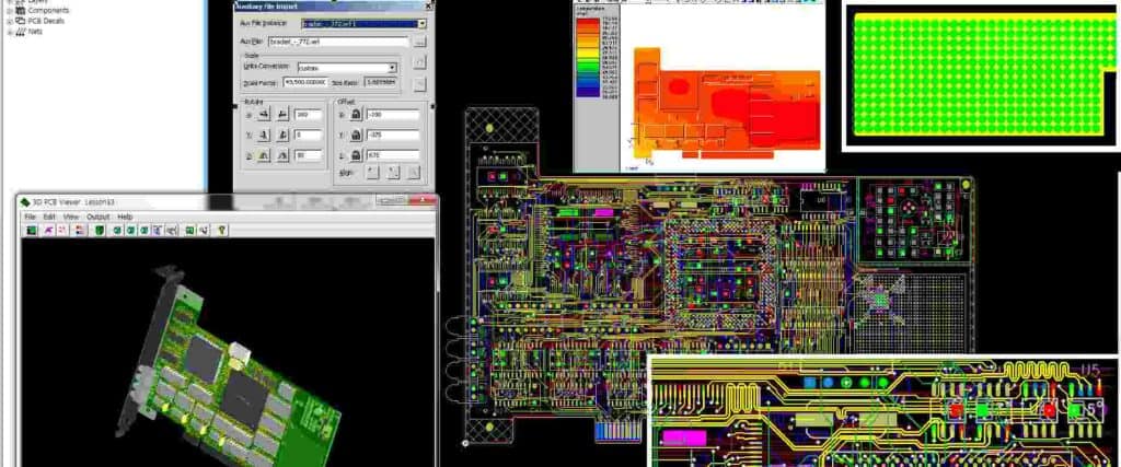
PCB tone control stereo layout is an essential aspect of designing high-quality audio systems. The layout of the printed circuit board (PCB) can significantly impact the performance of the tone control stereo system. The PCB layout design plays a crucial role in ensuring that the audio signals are transmitted accurately and without any interference.
The layout of the PCB should be designed to minimize the noise and interference that can occur in the audio signals. The tone control stereo system typically consists of various components, including resistors, capacitors, and transistors. Proper placement of these components on the PCB is vital to ensure that the audio signals are transmitted accurately and without any distortion. The layout should be designed to minimize the distance between the components and ensure that the signal traces are kept as short as possible.

Layout
When designing a PCB for a tone control stereo, there are a few key considerations to keep in mind. The layout of the PCB is critical for ensuring that the tone control circuit functions properly and that the stereo sound quality is not compromised.
PCB Design
The first step in designing a PCB for a tone control stereo is to choose the appropriate size and shape for the board. The board should be large enough to accommodate all of the necessary components, but not so large that it becomes unwieldy or difficult to work with.
Once the size and shape of the board have been determined, it is important to carefully place all of the components in their proper locations. This will help to ensure that the circuit functions properly and that there are no interference issues.
Tone Control Circuit
The tone control circuit is a critical component of the stereo system, and it is important to design it carefully. The circuit should be designed to provide a wide range of tone control options, including bass, treble, and midrange adjustments.
When designing the tone control circuit, it is important to choose high-quality components that will provide a clean, clear sound. The circuit should also be designed to minimize noise and interference, which can degrade the sound quality of the stereo.
In summary, designing a PCB for a tone control stereo requires careful attention to detail and a thorough understanding of the components involved. By following best practices for PCB design and tone control circuit design, it is possible to create a high-quality stereo system that provides excellent sound quality and a wide range of tone control options.
Stereo

Stereo Circuit Design
When designing a stereo tone control PCB layout, it is important to consider the overall circuit design. The stereo circuit design should be balanced and provide equal power to both left and right channels. It should also be designed to minimize crosstalk between the two channels.
One way to achieve this is by using a dual potentiometer for each tone control. This will ensure that the same amount of resistance is used in both channels, resulting in equal power distribution. Additionally, using a dual-gang potentiometer will help reduce crosstalk between the channels.
Another important factor to consider is the placement of the tone control circuitry within the overall PCB layout. It is recommended to place the tone control circuitry close to the input stage of the amplifier, as this will help minimize noise and interference.
When designing the stereo tone control PCB layout, it is also important to consider the type of tone control circuitry being used. For example, a passive tone control circuit may be simpler and more cost-effective, but may result in a loss of signal strength. On the other hand, an active tone control circuit may provide better signal strength, but may be more complex and expensive to implement.
Overall, the stereo circuit design should be carefully planned and implemented to ensure optimal performance and minimal interference between the left and right channels.

