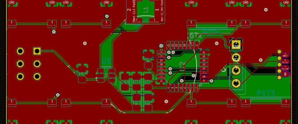
PCB 4 layer design is a critical aspect of printed circuit board (PCB) production. It involves creating a PCB with four layers of copper traces, which are separated by insulating material. The design process is complex and requires a deep understanding of PCB manufacturing, as well as the specific requirements of the circuit being designed.
The use of four-layer PCBs has become increasingly popular over the years, due to their ability to handle more complex circuits and higher density designs. They are commonly used in applications such as telecommunications, computing, and medical devices. The additional layers provide more space for routing traces, which can help reduce noise and interference, as well as improve signal integrity. Additionally, the four-layer design can help reduce the size of the PCB, making it more compact and easier to fit into smaller devices.
Benefits of 4 Layer PCB Design
Improved Signal Integrity
One of the main benefits of 4 layer PCB design is improved signal integrity. With 4 layers, it is possible to separate the power and ground planes from the signal traces, which reduces the amount of noise and interference that can affect the signals. This leads to better signal quality and more reliable performance.
Reduced Electromagnetic Interference
Another benefit of 4 layer PCB design is reduced electromagnetic interference. By separating the power and ground planes from the signal traces, it is possible to reduce the amount of electromagnetic interference that can affect the signals. This is particularly important in high-speed designs where even small amounts of interference can cause problems.
Higher Component Density
Finally, 4 layer PCB design allows for higher component density. With more layers available, it is possible to place more components on the board without sacrificing signal quality or increasing the risk of interference. This can be particularly important in complex designs where space is at a premium.
Overall, 4 layer PCB design offers a number of benefits over simpler designs. By improving signal integrity, reducing electromagnetic interference, and allowing for higher component density, it is possible to create more reliable and efficient PCBs that can meet the demands of even the most complex applications.
Design Considerations
When designing a PCB with four layers, there are several design considerations to keep in mind. These considerations include layer stackup, trace width and spacing, and via placement.
Layer Stackup
The layer stackup is the arrangement of the four layers in the PCB. The most common arrangement for a four-layer PCB is signal-ground-power-signal, where the signal layers are sandwiched between the ground and power planes. This arrangement provides good signal integrity and noise immunity.
Trace Width and Spacing
The trace width and spacing are critical factors in a PCB design. The trace width and spacing determine the impedance of the traces and the amount of current they can carry. The trace width should be chosen based on the current carrying capacity of the trace, while the spacing should be chosen based on the voltage isolation requirements.
Via Placement
Vias are used to connect the different layers of the PCB. The placement of vias is critical to the performance of the PCB. Vias should be placed close to the components they are connecting, and they should be placed in a way that minimizes the impedance of the connection.
In summary, when designing a four-layer PCB, it is important to consider the layer stackup, trace width and spacing, and via placement. By keeping these considerations in mind, you can create a PCB that performs well and meets the requirements of your project.
Manufacturing Process

Drilling and Plating
The first step in PCB 4 layer design manufacturing is drilling and plating. Holes are drilled in the board, and a thin layer of copper is deposited on the surface. The holes are then plated with copper to create electrical connections between the layers.
Lamination
The next step in the manufacturing process is lamination. The layers of the board are laminated together using heat and pressure. This process creates a strong bond between the layers and ensures that the electrical connections between the layers are secure.
Etching
After lamination, the board is etched to remove the unwanted copper. The etching process is done using a chemical solution that dissolves the copper that is not needed. The remaining copper forms the traces and pads on the board.
Plating
The final step in the manufacturing process is plating. A thin layer of gold or other metal is plated onto the surface of the board to protect the copper from oxidation and to improve the conductivity of the board.
Overall, the manufacturing process for PCB 4 layer design is complex and requires a high level of precision and expertise. By following these steps, manufacturers can produce high-quality boards that meet the needs of their customers.
Testing and Validation
Electrical Testing
Before the PCB 4 layer design is manufactured, it is important to conduct electrical testing to ensure that the design is functioning as intended. Electrical testing includes checking for short circuits, open circuits, and continuity of all the traces. This testing is typically done using a multimeter or an automated testing machine.
During the testing process, it is important to ensure that the power and ground planes are properly connected and that there are no breaks or gaps in the planes. Additionally, it is important to check that the voltage and current levels are within the specified limits.
Signal Integrity Analysis
Signal integrity analysis is a critical step in the validation process of a PCB 4 layer design. The goal of signal integrity analysis is to ensure that the signals are transmitted with minimal distortion and interference. This is especially important for high-speed designs.
Signal integrity analysis involves simulating the design using software tools to identify any potential issues such as reflections, crosstalk, and impedance mismatches. The simulation results are then used to optimize the design and make any necessary changes.
Once the design has been optimized, it is important to perform signal integrity testing to validate the simulation results. This testing involves measuring the actual signals on the board and comparing them to the simulated results. If there are any discrepancies between the two, further optimization is required.
In conclusion, testing and validation are critical steps in the PCB 4 layer design process. Electrical testing and signal integrity analysis are two important aspects of this process that help ensure the design is functioning as intended. By following these steps, designers can ensure that their designs are optimized for performance and reliability.
Conclusion
In conclusion, a 4-layer PCB design offers a number of advantages over 2-layer and 3-layer designs. By distributing the components across multiple layers, it is possible to reduce the size of the board, improve signal integrity, and reduce the amount of noise and interference. This can lead to better performance and reliability.
However, designing a 4-layer PCB requires careful planning and attention to detail. It is important to consider factors such as the placement of components, the routing of traces, and the use of ground planes and power planes. By following best practices and guidelines, it is possible to create a design that meets the requirements of the application and performs reliably.
Some key considerations to keep in mind when designing a 4-layer PCB include:
- Use of ground and power planes to reduce noise and interference
- Careful placement of components to minimize signal paths and reduce crosstalk
- Use of high-quality materials and manufacturing processes to ensure reliability
- Thorough testing and validation to ensure that the design meets the requirements of the application
Overall, a 4-layer PCB design can be an excellent choice for many applications. By following best practices and guidelines, it is possible to create a design that meets the requirements of the application and performs reliably.
