SMD PCB assembly is a process of assembling electronic components on the surface of a printed circuit board (PCB). This process involves placing and soldering small components on the surface of the PCB, rather than inserting them through holes in the board. SMD PCB assembly has become the preferred method of assembling PCBs due to its many advantages over traditional through-hole assembly.
One of the main advantages of SMD PCB assembly is that it allows for a higher component density on the board. This means that more components can be placed on a smaller area of the board, which can be particularly useful in compact electronic devices. Additionally, SMD components are typically smaller and lighter than through-hole components, making them ideal for portable devices. Another advantage of SMD PCB assembly is that it can be automated, which can increase efficiency and reduce costs.

What is SMD PCB Assembly?
Surface mount device (SMD) PCB assembly is a method of assembling electronic circuits where the components are mounted directly onto the surface of the printed circuit board (PCB). This is in contrast to through-hole technology (THT), where the components are inserted into holes drilled into the PCB.
SMD components are typically much smaller than their THT counterparts, which means that they can be placed much closer together on the board. This allows for much higher component density and smaller PCB sizes. SMD assembly also allows for automated assembly, which can significantly reduce production costs.
There are many different types of SMD components, including resistors, capacitors, diodes, transistors, and integrated circuits. These components are typically mounted onto the PCB using a reflow soldering process, where the board is heated to a temperature that melts the solder and fuses the components to the board.
Overall, SMD PCB assembly is a versatile and cost-effective method of assembling electronic circuits, and is widely used in a variety of industries, including consumer electronics, automotive, aerospace, and more.
Advantages of SMD PCB Assembly
SMD (Surface Mount Device) PCB assembly has become the preferred method of PCB assembly in recent years. Here are some of the advantages of using SMD PCB assembly:
-
Higher Component Density: SMD components are smaller in size and can be placed closer together on the PCB, resulting in higher component density on the board. This means that more components can be placed on a smaller board, reducing the overall size of the product.
-
Improved Performance: SMD components have shorter lead lengths and are placed closer to the board, resulting in less parasitic capacitance and inductance. This leads to improved signal integrity and better performance of the product.
-
Cost-Effective: SMD PCB assembly is a cost-effective method of assembly, as it requires less manual labor and fewer components. This results in reduced assembly time and lower assembly costs.
-
Higher Production Rates: SMD PCB assembly can be automated, resulting in higher production rates and faster turnaround times. This is particularly important for high-volume production runs.
-
Improved Reliability: SMD components are less prone to mechanical stress and vibration, resulting in improved reliability of the product. Additionally, SMD components are less likely to be damaged during the assembly process, resulting in fewer defects and higher yield rates.
In conclusion, SMD PCB assembly offers several advantages over traditional through-hole PCB assembly, including higher component density, improved performance, cost-effectiveness, higher production rates, and improved reliability.
SMD PCB Assembly Process

Surface Mount Device (SMD) PCB assembly is a process of mounting electronic components directly onto the surface of a printed circuit board (PCB). SMD components are small in size and are mounted using automated pick and place machines. The process involves the following steps:
-
Stenciling: The first step in the SMD PCB assembly process is stenciling. A stencil is used to apply solder paste onto the PCB. The stencil is aligned with the PCB and solder paste is applied through the openings in the stencil onto the pads where the components will be mounted.
-
Component Placement: The second step is component placement. The pick and place machine picks up the SMD components from the reels or trays and places them accurately onto the solder paste on the PCB. The machine uses vision systems to ensure accurate placement.
-
Reflow Soldering: The third step is reflow soldering. The PCB is passed through a reflow oven where the solder paste is heated and melted. The SMD components are soldered onto the PCB during this process.
-
Inspection: The last step is inspection. The PCB is inspected to ensure that all components are correctly placed and soldered. Automated optical inspection (AOI) machines are used to detect any defects in the assembly.
SMD PCB assembly is widely used in the electronics industry due to its many advantages, including smaller size, higher component density, and lower cost. This process allows for faster and more efficient assembly of electronic devices.
SMD Components
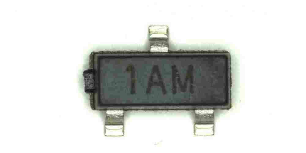
SMD (Surface Mount Device) components are small electronic components that are mounted directly onto the surface of a PCB (Printed Circuit Board). They are widely used in modern electronic devices due to their small size, high performance, and low cost. SMD components are available in a variety of sizes and shapes, ranging from tiny 0201 packages to large QFP (Quad Flat Package) and BGA (Ball Grid Array) packages.
SMD components are typically classified into two categories: passive components and active components. Passive components include resistors, capacitors, inductors, and diodes, while active components include transistors, ICs (Integrated Circuits), and other complex devices.
One of the advantages of SMD components is their small size, which allows for higher component density on a PCB. This results in smaller and more compact electronic devices. Additionally, SMD components are easier and faster to assemble than through-hole components, as they can be automatically placed and soldered using pick-and-place machines.
When designing a PCB with SMD components, it is important to consider the placement and orientation of the components, as well as the thermal management of the board. Proper layout and design can help to reduce the risk of component damage due to high temperatures or mechanical stress.
In summary, SMD components are an essential part of modern electronics and offer many advantages over through-hole components. They are small, cost-effective, and easy to assemble, making them ideal for a wide range of applications.
Soldering Techniques for SMD PCB Assembly
Soldering is a crucial step in SMD PCB assembly. It is essential to ensure that the components are securely attached to the board, and the joints are strong and reliable. Here are some soldering techniques that can help you achieve high-quality results.
1. Surface Preparation
Before soldering, it is essential to prepare the surface of the board and the components. Make sure that the surface is clean and free from any dirt, dust, or grease. Use a flux to remove any oxidation on the surface and ensure a strong bond between the components and the board.
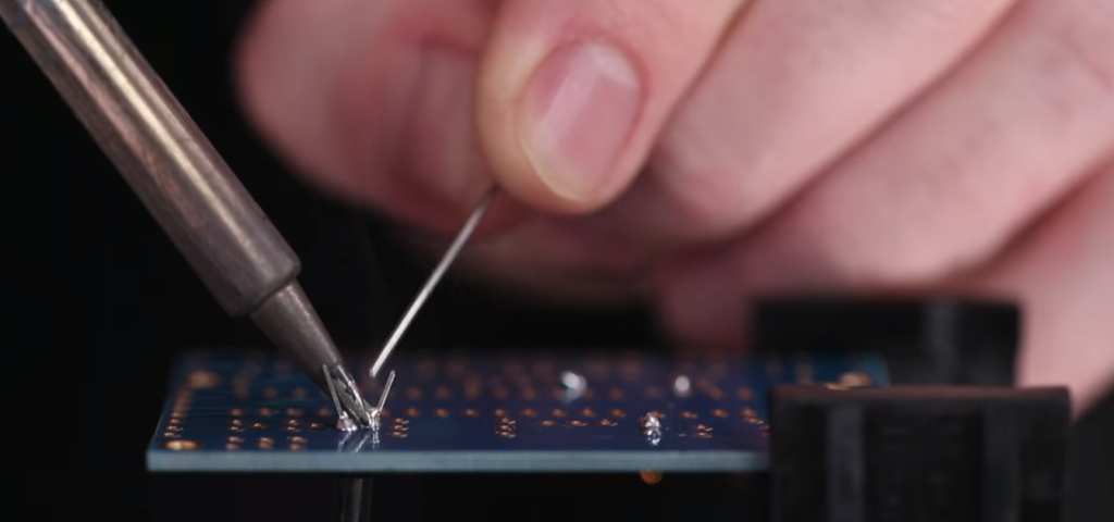
2. Soldering Iron
Choose a soldering iron with a fine tip for SMD components. The tip should be clean and tinned with solder. The temperature of the iron should be set according to the type of component and the size of the board. Too much heat can damage the components, while too little heat can result in poor solder joints.
3. Soldering Technique
The technique used for soldering SMD components is different from through-hole components. Apply a small amount of solder to the tip of the iron and touch it to the joint. The solder should melt and flow around the joint, forming a smooth and shiny surface. Avoid applying too much solder, as it can cause bridges between the pins.
4. Inspection
After soldering, inspect the joints carefully to ensure that they are strong and reliable. Look for any cracks, cold joints, or bridges between the pins. Use a magnifying glass to inspect the joints more closely.
5. Reflow Soldering
Reflow soldering is a technique used for SMD PCB assembly, where the components are soldered using a reflow oven. This method is useful for large-scale production and can result in high-quality and consistent results. However, it requires specialized equipment and expertise.
In conclusion, soldering is a critical step in SMD PCB assembly. By following these techniques, you can achieve high-quality and reliable results. Always ensure that the components are securely attached to the board and the joints are strong and consistent.
