Board circuit design is an essential aspect of modern electronics. It involves the process of designing and developing printed circuit boards (PCBs) that serve as the foundation for electronic devices. The design process involves a careful consideration of various factors, including the functionality of the device, the size and shape of the board, and the materials used.
Effective board circuit design requires a deep understanding of electrical engineering principles, as well as knowledge of the latest design tools and software. Designers must be able to translate complex technical specifications into functional circuit board designs that meet the needs of their clients. This involves a collaborative process that often involves close communication between the designer and the client, as well as other members of the design team. Ultimately, the goal of board circuit design is to create functional, reliable, and cost-effective electronic devices that meet the needs of consumers and businesses alike.

Basics of Board Circuit Design
Understanding Circuit Design
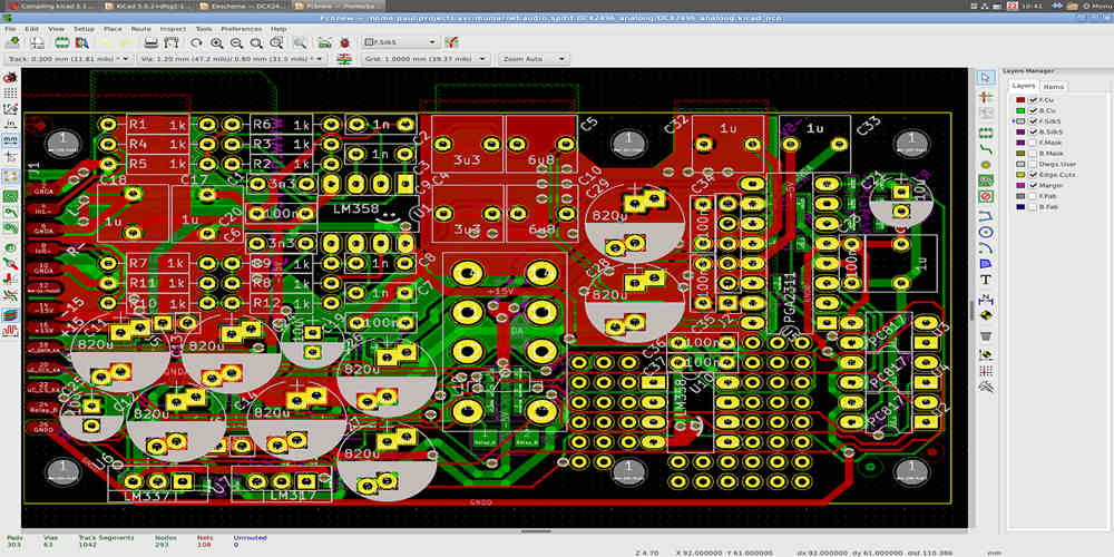
Board circuit design is the process of creating a printed circuit board (PCB) that connects electronic components using conductive pathways. The design process involves creating a schematic diagram, which shows the connections between components and the flow of electricity. The schematic diagram is then used to create the PCB layout, which is the physical representation of the circuit design.
When designing a circuit, it’s important to consider the specifications of the components being used, such as voltage and current requirements, as well as the overall functionality of the circuit. It’s also important to consider factors such as size, cost, and manufacturability.
Types of Circuit Boards
There are several types of circuit boards that can be used in circuit design, each with its own advantages and disadvantages:
-
Single-sided PCBs: These are the simplest type of PCB, with components mounted on one side of the board and conductive pathways on the other. They are inexpensive and easy to manufacture, but are limited in their complexity and can be prone to noise and interference.
-
Double-sided PCBs: These have components mounted on both sides of the board, with conductive pathways connecting them. They are more complex than single-sided PCBs, but offer greater flexibility and can handle higher frequencies.
-
Multi-layer PCBs: These have multiple layers of conductive pathways separated by insulating layers. They are used in complex circuits that require high density and low noise.
In conclusion, understanding the basics of board circuit design is essential for creating functional and efficient electronic circuits. By considering the specifications of components and the type of circuit board being used, designers can create circuits that meet their requirements while also being cost-effective and manufacturable.
Components of Board Circuit Design

Integrated Circuits
Integrated circuits (ICs) are the building blocks of modern electronics. They are used to create complex circuits that would be difficult or impossible to build using discrete components. ICs are small, lightweight, and consume very little power, making them ideal for use in portable devices. They are also highly reliable and can be mass-produced at low cost.
There are many different types of ICs, each designed for a specific purpose. Some of the most common types of ICs used in board circuit design include microprocessors, memory chips, amplifiers, and voltage regulators. Microprocessors are used to control the operation of electronic devices, while memory chips are used to store data. Amplifiers are used to boost the signal strength of electronic circuits, while voltage regulators are used to maintain a constant voltage level.
Passive Components
Passive components are electronic components that do not require a power source to function. They are used to control the flow of electrical current in a circuit. Some of the most common types of passive components used in board circuit design include resistors, capacitors, and inductors.
Resistors are used to limit the flow of electrical current in a circuit. They are commonly used to control the brightness of LEDs or to set the gain of an amplifier. Capacitors are used to store electrical charge and are commonly used in power supplies and filters. Inductors are used to store energy in a magnetic field and are commonly used in power supplies and filters.
Active Components
Active components are electronic components that require a power source to function. They are used to amplify or switch electrical signals. Some of the most common types of active components used in board circuit design include transistors, diodes, and operational amplifiers.
Transistors are used to amplify or switch electrical signals. They are commonly used in amplifiers, oscillators, and digital circuits. Diodes are used to control the flow of electrical current in a circuit. They are commonly used in rectifiers and voltage regulators. Operational amplifiers are used to amplify or filter electrical signals. They are commonly used in audio and video circuits.
In summary, the components of board circuit design include integrated circuits, passive components, and active components. Each type of component serves a specific purpose and is essential for the proper functioning of electronic devices.
Design Process for Board Circuit Design

Schematic Capture
The first step in the design process for board circuit design is schematic capture. This involves creating a visual representation of the circuit using a software tool. During schematic capture, the designer should consider the functionality of the circuit, the components needed, and the connections between them. It is important to ensure that the schematic is accurate and complete before moving on to the next step.
PCB Layout Design
Once the schematic is complete, the next step is to create the physical layout of the circuit board. This involves placing the components on the board and routing the connections between them. During this step, the designer should consider factors such as the size and shape of the board, the location of connectors and mounting holes, and the placement of components to minimize noise and interference. It is important to ensure that the layout is optimized for manufacturability and testing.
Prototyping
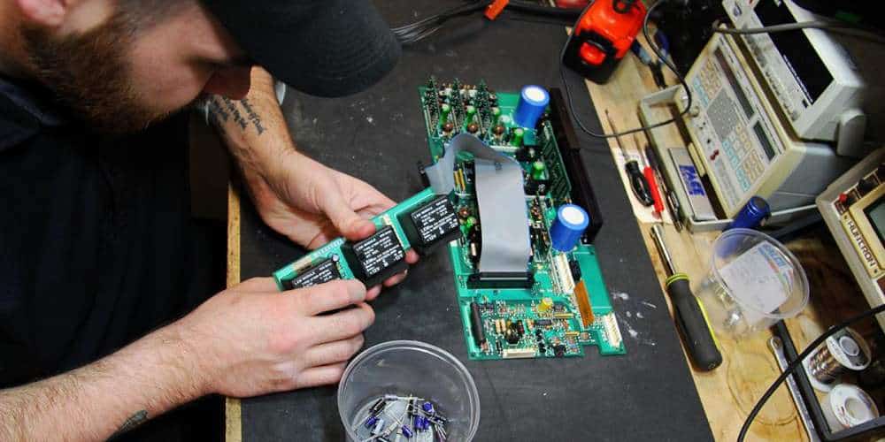
After the PCB layout is complete, the next step is to create a prototype of the board. This involves manufacturing the board and assembling the components onto it. The prototype should be tested to ensure that it functions as intended and meets the design specifications. Any issues or errors should be addressed before moving on to the final step.
Testing
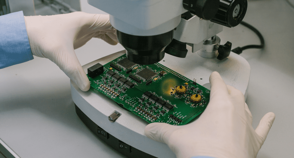
The final step in the design process is testing. This involves verifying that the board meets the requirements and specifications outlined in the design. The board should be tested for functionality, performance, and reliability. Any issues should be identified and addressed before the board is released for production.
In conclusion, the design process for board circuit design involves several steps, including schematic capture, PCB layout design, prototyping, and testing. Each step is critical to ensuring that the final product meets the design specifications and is optimized for manufacturability and testing. By following a structured design process, designers can create high-quality circuit boards that meet the needs of their clients and end-users.
Advanced Techniques for Board Circuit Design

High-Speed Design
High-speed design is an essential aspect of board circuit design. It involves the design of circuits that operate at high frequencies, such as those used in digital signal processing, telecommunications, and data transmission. To achieve high-speed design, the following techniques can be used:
- Minimizing parasitic capacitance and inductance
- Using impedance matching techniques
- Implementing signal termination to reduce reflections
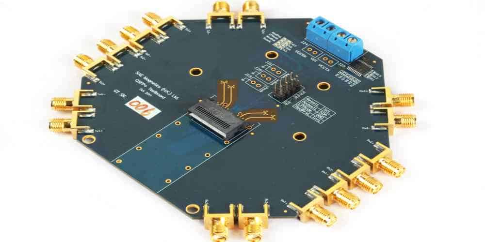
- Using high-speed data transmission standards, such as PCI Express, USB 3.0, and SATA
RF Design
RF design is the design of circuits that operate at radio frequencies. It is used in applications such as wireless communication, radar, and satellite communication. To achieve RF design, the following techniques can be used:
- Using impedance matching techniques
- Implementing signal termination to reduce reflections
- Using RF simulation software to optimize the design
- Using high-quality RF components, such as filters, amplifiers, and mixers
Power Supply Design
Power supply design is the design of circuits that provide power to the board and its components. It is important to design a stable and efficient power supply to ensure the reliable operation of the board. To achieve power supply design, the following techniques can be used:
- Using voltage regulators to regulate the voltage
- Using capacitors and inductors to filter out noise and ripple
- Using high-quality power components, such as transformers and rectifiers
- Implementing thermal management techniques to prevent overheating
In conclusion, advanced techniques for board circuit design involve high-speed design, RF design, and power supply design. By using these techniques, designers can create circuits that are reliable, efficient, and high-performing.
Future of Board Circuit Design

Emerging Technologies
The field of board circuit design is constantly evolving with the introduction of new technologies. One of the emerging technologies that is gaining traction in the industry is 3D printing. With 3D printing, it is possible to create complex shapes and designs that were not possible with traditional manufacturing methods. This technology has the potential to significantly reduce the time and cost of prototyping, making it an attractive option for startups and small businesses.
Another emerging technology that is set to change the landscape of board circuit design is artificial intelligence (AI). AI can be used to optimize the design process, reducing the time and cost of development. It can also be used to improve the performance of the final product by analyzing data and making real-time adjustments.
Industry Trends
The board circuit design industry is moving towards miniaturization and portability. With the rise of the Internet of Things (IoT), there is a growing demand for small, lightweight, and energy-efficient devices that can be connected to the internet. This trend is driving the development of new materials and manufacturing processes that can produce smaller and more complex circuits.
Another trend in the industry is the move towards more environmentally-friendly manufacturing processes. With concerns about climate change and sustainability, companies are looking for ways to reduce their carbon footprint. This has led to the development of new materials and manufacturing processes that are more energy-efficient and produce less waste.
In conclusion, the future of board circuit design looks promising with the introduction of new technologies and the industry’s focus on miniaturization and sustainability. As the industry continues to evolve, it will be important for designers to stay up-to-date with the latest trends and technologies to remain competitive.

