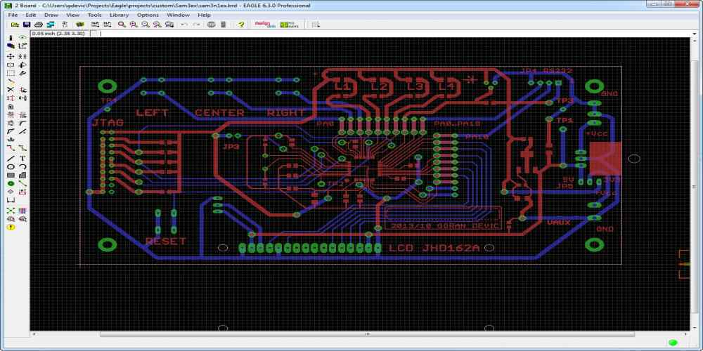
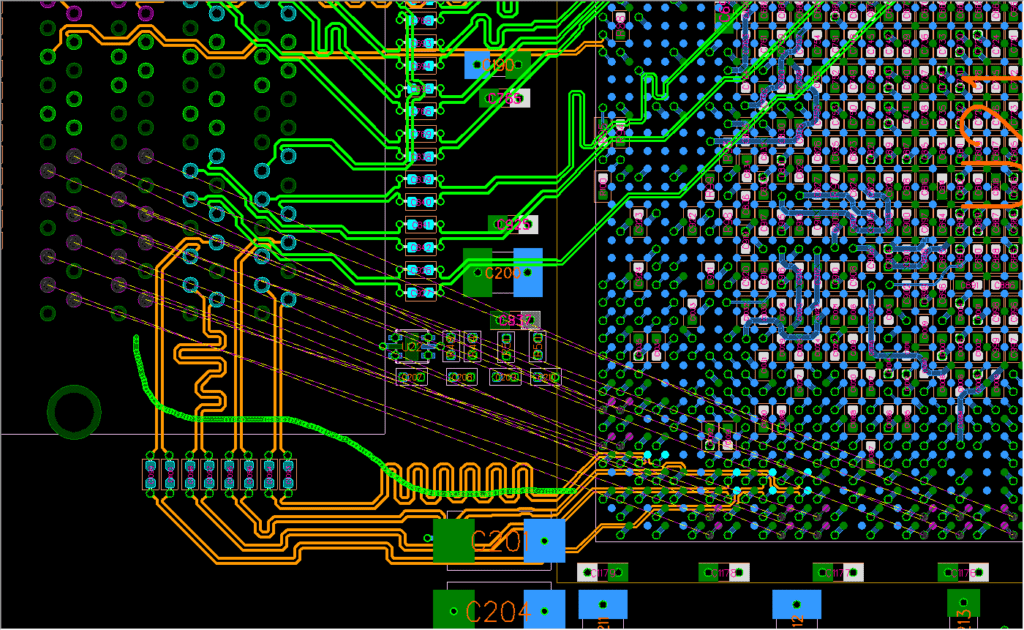
Digital logic and circuit design is an essential aspect of modern technology. It deals with the design and analysis of digital circuits, which are used in various electronic devices, including computers, smartphones, and televisions. Digital circuits are composed of logic gates, which are the building blocks of digital systems.
Digital logic is based on Boolean algebra, which is a mathematical system that deals with logic operations. The basic logic gates include AND, OR, and NOT gates, which are used to perform logical operations on binary inputs. These gates can be combined to form more complex circuits, such as adders, multiplexers, and flip-flops. Circuit design involves selecting the appropriate gates and arranging them to perform a specific function.
The field of digital logic and circuit design is constantly evolving, with new technologies and techniques being developed to improve the performance and efficiency of digital systems. Understanding the principles of digital logic and circuit design is crucial for anyone involved in the design, development, or maintenance of electronic devices.

Digital Logic Fundamentals
Boolean Algebra
Boolean Algebra is a mathematical system used in digital electronics to manipulate logical expressions. It consists of three basic operations: AND, OR, and NOT. These operations are represented by the symbols ∧, ∨, and ¬, respectively.
The rules of Boolean Algebra are simple and straightforward. They are based on the laws of logic and can be used to simplify complex logic expressions. Some of the important rules of Boolean Algebra are:
- De Morgan’s Laws
- Idempotence
- Commutativity
- Associativity
- Distributivity
Logic Gates
Logic gates are electronic circuits that perform logical operations on one or more inputs. They are the building blocks of digital circuits. There are several types of logic gates, including AND, OR, NOT, NAND, NOR, XOR, and XNOR gates. Each gate has a specific truth table that defines its behavior.
Combinational Logic
Combinational logic is a type of digital logic that combines logic gates to produce a specific output based on the input values. The output of a combinational logic circuit depends only on the current input values and not on any previous input values. Examples of combinational logic circuits include adders, subtractors, and multiplexers.
Sequential Logic
Sequential logic is a type of digital logic that combines combinational logic circuits with memory elements to produce a specific output based on the current input values and the previous input values. The output of a sequential logic circuit depends on the current input values and the previous input values. Examples of sequential logic circuits include flip-flops, counters, and registers.
In conclusion, understanding the fundamentals of digital logic is essential for designing and building digital circuits. Boolean Algebra, logic gates, combinational logic, and sequential logic are the building blocks of digital circuits. By mastering these concepts, one can design and build complex digital circuits with ease.
Circuit Design

When designing digital circuits, the goal is to create a circuit that performs a specific function. This can be achieved through the use of various components, such as logic gates, multiplexers, and flip-flops. In this section, we will discuss some of the most common components used in digital circuit design.
Karnaugh Maps
Karnaugh maps, also known as K-maps, are a graphical representation of Boolean functions. They are used to simplify logic expressions and minimize the number of gates needed to implement a circuit. K-maps are especially useful for circuits with four or more inputs.
Multiplexers and Demultiplexers
Multiplexers, or MUXes, are digital circuits that select one of several input signals and forward the selected input to the output. Demultiplexers, or DEMUXes, do the opposite; they take a single input and distribute it to one of several outputs. These components are commonly used in digital communication systems, such as telephone networks.
Adders and Subtractors
Adders and subtractors are circuits that perform addition and subtraction operations on binary numbers. Half-adders and full-adders are used for addition, while subtractors use a combination of adders and inverters. These circuits are essential for arithmetic operations in digital systems.
Flip-Flops
Flip-flops are circuits that store a single bit of information. They are commonly used as memory elements in digital systems, such as registers and counters. There are several types of flip-flops, including D flip-flops, JK flip-flops, and T flip-flops.
In conclusion, understanding the function and operation of these components is crucial for designing digital circuits. By using Karnaugh maps, multiplexers, adders, subtractors, and flip-flops, designers can create efficient and effective circuits for a variety of applications.
Advanced Topics

Memory and Storage
Memory and storage are essential components of any digital system. Memory refers to the temporary storage of data, while storage refers to the permanent storage of data. In digital logic and circuit design, memory is typically implemented using flip-flops or registers, while storage is implemented using non-volatile memory devices such as flash memory or hard disk drives.
Programmable Logic Devices
Programmable logic devices (PLDs) are integrated circuits that can be programmed to perform specific logic functions. PLDs are used to implement complex logic functions that cannot be easily implemented using basic logic gates. Examples of PLDs include field-programmable gate arrays (FPGAs) and complex programmable logic devices (CPLDs).
Timing and Clocks
Timing and clocks are critical components of any digital system. Timing refers to the synchronization of signals within a digital system, while clocks refer to the periodic signals that synchronize the operation of digital circuits. Timing and clocks are crucial for ensuring that digital circuits operate correctly and reliably.
Hardware Description Languages
Hardware description languages (HDLs) are used to describe digital circuits at a high level of abstraction. HDLs allow designers to specify the behavior of digital circuits using a textual or graphical representation. Examples of HDLs include Verilog and VHDL.
In conclusion, these advanced topics in digital logic and circuit design are essential for designing complex digital systems. By understanding memory and storage, programmable logic devices, timing and clocks, and hardware description languages, designers can create digital systems that are efficient, reliable, and cost-effective.

