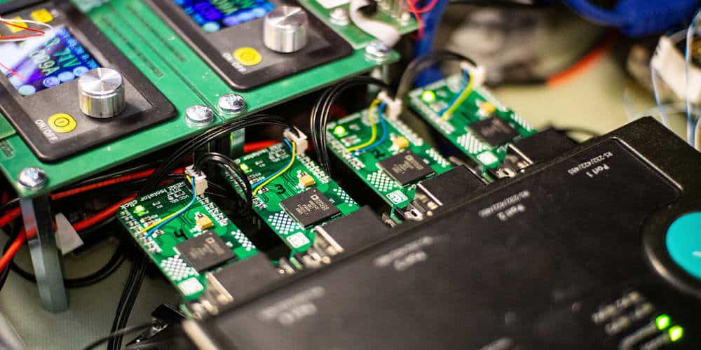
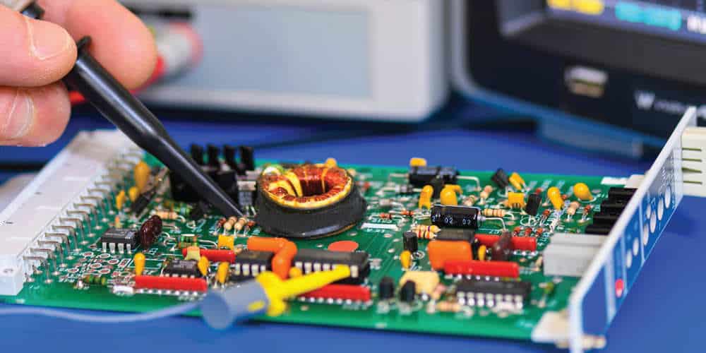
An FCT test, also known as a functional circuit test, is a type of examination conducted on printed circuit boards (PCBs) during the production process. This test aims to detect any shorts or separate circuits in the Printed circuit board and confirm that the board performs as intended. FCT is a critical quality assurance component for printed circuit boards, generally carried out after the soldering (fusing) process has been completed.
PCBs are vital to many industries as they enable electronic components to be connected through conductive pathways. These pathways are created by laminating copper sheets onto the circuit boards, enabling electric current to flow. In this way, PCBs have become the foundation for various electronic devices used across numerous industries.
Functional testing of printed circuit boards (PCBs) is a vital part of their production. These tests, conducted after the manufacturing process has been completed, ensure that the PCBs will function properly before they are released to the market. The functional testing of PCBs represents the final step between manufacturing (production) and the market.
Printed circuit board functional testing is used to verify that a printed circuit board (PCB) functions correctly. If you are interested in learning more about functional testing and want additional information on the subject, you can search for more details about PCB functional testing.

Design of FCT Testing PCB
One way to prioritize DFT (Design for Test) early on in the development process is by integrating the printed circuit board prototype model (design) with FCT (Functional Circuit Testing).
A popular FCT method is the bed-of-nails structure, which comprises pogo pins positioned to connect with test points on the bottom of the printed circuit board. This approach has several benefits compared to other methods of accessing the circuitry during the early stages of development.
While it is possible to access specific points through soldered wires, this method may require a highly proficient technician and may also risk damaging costly components. Utilizing a pin board, on the other hand, allows for multiple uses without causing any harm to the components.
Fixture Design Of FCT Testing PCB
A bed-of-nails functional circuit test with a high density of test points can be beneficial during the early design stages for crucial subsystems. One benefit of this approach is that the pogo pins are usually arranged in a grid pattern, which allows for using a standard pogo pin board alongside separate control boards. This means that it is possible to make any changes to the control boards without having to alter all of them. As a result, the designer can utilize the same pogo pin pad in the overall prototyping process.
As the size of PCBs continues to decrease, it becomes increasingly difficult to utilize bed-of-nails testing, particularly when it comes to precise alignment. To mitigate this issue, it can be helpful to carefully plan the placement of test points at the outset of the design process.
One way for designers to ensure proper alignment of pin boards with the device under test is to cover test points with a sheet of thin tape. When the taped board is placed in the fixture, the pins will press against the tape and create indentations at the contact points. This method allows designers to verify the arrangement of the pins and make any necessary adjustments. Additionally, adding headers to FCT control boards with breakouts provides for measurement of connections with the printed circuit board under test while in the fixture.
Designers often utilize a bottom-up design approach when assembling a pinboard with a particular Printed Circuit Board (PCB) assembly, allowing for more efficient testing and optimal alignment. A press fixture designed to accommodate this type of design can be handy; it allows for even pressure to be applied and ensures that all test points on the printed circuit board under test make good contact.
Importance of FCT Testing PCB
The PCB manufacturing process includes FCT to verify that the boards function correctly and do not have any defects. By conducting this test, potential issues with the PCB can be detected and addressed before they are shipped to the customer, ultimately saving money and time.
Requirements for functional testing PCB
To perform functional testing, a test fixture is necessary for securing the PCB during the testing process, probe cards are used to establish a connection between the test equipment and the PCB, and specialized test software allows for control over the testing procedure and data collection.
Benefits OF FCT Testing PCB Or Functional Tests
Other functional testing methods include the hot mock-up(simulated)test, which confirms that the PCB is functioning correctly. More comprehensive functional testing may involve subjecting the printed circuit board(PCB) assembly to various operational tests across multiple conditions.
Functional testing has many advantages such as:
- Instead of using costly and actual testing equipment, functional testing of a PCB assembly can be done by creating a simulated operating environment. This not only saves the customer money but also allows for efficient testing.
- By utilizing this approach, costly system tests can be avoided, ultimately saving the customer both financial resources and time.
- Through the use of this testing method, it is feasible to test a significant portion of the product, ranging from 50-100%, before it is shipped to the customer. This can significantly reduce the effort and time required for the customer to test and troubleshoot the PCB assembly.
- Skilled professionals can utilize a functional test to extract the highest level of productivity, making it the most effective form of testing besides a complete system test program.
- Functional testing, in conjunction with ICT(Information and Communications Technology)and in-circuit tests, can help ensure that a PCB assembly is error-free and more durable.
Using FCT Testing PCB
Functional testing allows for the simulation or emulation of a product’s operational environment to verify its proper functioning. This may include using devices that interact with the PCB assembly being tested, such as testing the efficient performance of a power supply with essential loads.
Functional testing involves exposing a (PCB) printed circuit board assembly to a series of signals at different power levels and observing the responses to verify proper functioning. The customer often specifies the sequence, procedure, and test method. Through functional testing, it’s possible to identify issues such as parametric failures, incorrect component values, and breakdowns.
Functional tests can be automated by production line operators using test software or firmware and computers. These tests may utilize instruments such as communication ports, digital millimeters, and IO boards. They may involve software and fixtures that connect various devices to the PCB assembly being tested.
Firmware for testing purposes is developed by engineers using programming languages such as Java, C, or Perl. This firmware is then run on a computer, which sends commands to a controller. The board being tested is then checked against certain specifications by the receiving test panel to determine if it passes or fails.
To ensure the reliability and effectiveness of our printed circuit board model and assembly operations, we prioritize functional testing for our customers. This allows us to adapt to the diverse needs of our client base, as we offer a broad range of PCB products to a varied group of customers. With a wealth of knowledge, expertise, and experience at our disposal, we can accommodate the unique requirements of each customer.
Additional FCT Testing PCB

In addition to the functional circuit test, there are various significant tests for printed circuit boards, such as:
1. Micro-sectioning analysis
By slicing open the printed circuit board, one can scrutinize its internal structure and identify any potential issues.
While this method may harm the board, it can reveal valuable insights about the assembling process that cannot be obtained through other means. For instance, the technician can detect gaps in the soldering or determine if the copper wires are insufficiently thin.
2. FCT Test–X-ray inspection
A non-invasive method, this technique employs high-voltage X-rays that pass through the printed circuit board and cast a shadow on the film or a digital sensor. By utilizing this method, we can uncover internal features like gaps in soldered connections and external elements like misaligned or absent components.
3. FCT Test–PCB Contamination Test
To check for the presence of outside particles on the crust of the printed circuit board, a contamination test can be performed. These particles can potentially lead to electrical faults or signal quality issues, so it is essential to identify them. A dust wand is a standard tool used for this purpose.
4. PCB solderability test
The purpose of a solderability test is to assess whether the printed circuit board can be soldered. This is critical because if the PCB cannot be soldered, It will not function. One common way to conduct this test is by using a soldering tool.
5. FCT Test points
Now that the functional circuit test fixture has been covered, let’s delve into the test points. These are the specific locations on the PCB where voltage measurements can be taken, and they are often utilized to link various elements of the functional circuit test. A black or red dot generally identifies test points.
6. FCT Test–ICT test
This section focuses on the ICT(Information and Communication Technology test), designed to detect any short circuits between the many tracks on a PCB. The test involves applying high voltage in one way and determining the voltage in another. If a short is present, the electromotive force(voltage)will be less than expected.
The Information and Communication Technology test is crucial as it can identify shorts that cannot be seen with the naked eye. These shorts can lead to various issues, so it’s essential to ensure that your printed circuit board passes the ICT test.
Conclusion
Performing a Printed circuit board FCT test is vital during the manufacturing process of printed circuit boards (PCBs). This test ensures that the boards function correctly and are free of errors or defects.
If you’re searching for a reputable PCB manufacturer, it’s a good idea to inquire about their testing processes and whether they include an operational test of the boards. At our company, we prioritize quality and always have a full PCB functional circuit test in our fabrication processes.


