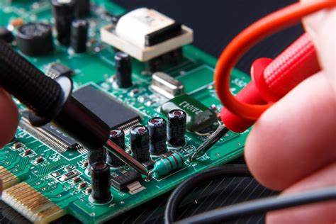
The first step in repairing electronic boards is to diagnose what is wrong with them. You can use a multimeter to determine if it is a circuit failure. If so, you can then repair the circuit by resoldering and reballing the damaged circuit. This will reconnect the circuit and allow electricity to flow again.
Troubleshooting PCB failures
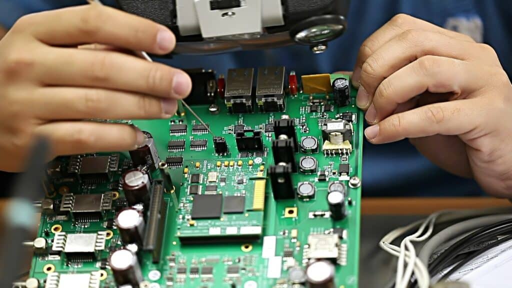
Troubleshooting PCB failures is a process that involves careful diagnosis and testing to find the cause of the failure. Identifying the exact location of the faulty part requires microscopic examination. The faulty part is then removed from the circuit board and replaced with a new one. While it’s difficult to pinpoint the exact location of a failure, there are several common signatures of faulty PCBs.
One of the most popular causes of PCB failure is physical damage caused by shock or pressure. For instance, the device could have been dropped from a great distance or hit by another object.
Fortunately, it is easy to repair many PCB failures. Although it can be expensive, it is usually much cheaper than replacing the entire board. Nonetheless, this option is not ideal for PCBs that have significant damage. In such cases, it’s best to seek professional assistance. A third-party repair company can provide this service at affordable prices.
Manufacturing errors can cause some PCB failures. For example, components may be soldered in the wrong location or go bad altogether. Printed circuit boards are a complex assembly of copper traces and insulators that connect densely packed components. Troubleshooting PCBs can be challenging, and a thorough understanding of the components and their functions is essential to ensuring a successful repair.
Cleaning up solder residues
When repairing electronic boards, cleaning up any flux residues is essential. These residues usually result from poor assembly techniques or negligence during the process. Unfortunately, they can also damage electronics, causing them to overheat and crash. Fortunately, there are many ways to clean PCB boards safely and effectively.
One option is to use deionized water. This solution can help you remove water-soluble flux residues. However, rosin-based fluxes require specific chemical solvents such as fluorocarbons. There are also no-clean fluxes, which don’t require cleaning after soldering.
Cleaning up solder residues after electronic board repair is critical for its longevity. If you have water on the board, it can interfere with the electrical connection, which could lead to corrosion. The best way to avoid this problem is to wipe off the board thoroughly with a lint-free cloth.
A second option is to clean up flux residues with rubbing alcohol. This is cheaper and more accessible. If you don’t have access to rubbing alcohol, you can use baking soda and a water paste to neutralize the flux residues. This will also help remove the flux that caused the board to become damaged.
As mentioned above, a clean circuit board has better conductivity. As a result, it’s more efficient. Unfortunately, it also prevents electrical leakage, which decreases the life expectancy of the electronic board. In addition, the electrical circuits on boards often become brittle, unstable, and need replacement. If you do not clean the board properly, it may result in expensive repairs.
Identifying the cause of failure
When repairing electronic boards, it is essential to identify the exact cause of the failure. In some cases, the failure may be due to a single component that is no longer functioning or a larger issue caused by the overall design of the board. Fortunately, many common components are easily identifiable.
The first step in identifying the cause of failure is visually inspecting the board. This can involve checking for obvious problems, including a poor solder joint. Identifying the exact cause of a failed PCB is essential because one bad component can affect many components on the board.
When repairing a PCB, it is essential to identify the exact cause to prevent repeat failure. Faulty components may result from overheating, voltage surges, corrosion, or aging. Using a meter can help you determine exactly what components have gone bad. Knowing how to spot the faulty component can prevent you from having to replace the whole board.
Another essential step in identifying the failure of electronic boards is the use of sophisticated test equipment. SEMs are an excellent tool for this. They can magnify defects to 120,000x and record the results on images. They can also determine if a component was heat-treated or not.
Repairing an electronic board can be a complicated process. The components on a PCB are complex and can range in size, configuration, and function. The main components of a PCB are a capacitor and copper tracing. In addition, the LED is a common component that allows current to flow in one direction.
Using a multimeter
There are hundreds of different uses for a multimeter, from testing individual components to diagnosing electrical circuits. It can help a fixer identify the most common problems and determine the proper solution to repair an electronic board. There are three basic functions that you should know to make the most of a multimeter.
First, you need to test the voltage and resistance of the board. Then, you can start using the red probe, which connects to the positive side. The other one, which is black, should connect to the negative side. The multimeter’s function button or knob will enable you to choose a measurement function. For example, connect the red probe to the test point if you’re testing for voltage. You can also connect the black probe to the common or ground.
If measuring current, ensure the multimeter’s continuity position is in the low resistance range. If it’s in the high resistance range, then the multimeter reads incorrectly. Try using a multimeter in the resistance or diode test mode when measuring current.
Another common problem with an electronic board is a faulty or damaged PCB. If the PCB is not working properly, it can be dangerous for all electronics. You can always consult an electrical schematic if you’re not confident in your diagnostic skills. The schematic will identify components on the board and their values. Then, you can use a multimeter to determine if the voltage of a component matches the voltage of the test point.
A multimeter with a COM port is ideal for measuring large currents. An mAVO port, on the other hand, is suitable for measuring resistance. The mAVO port can read up to 200mA.
Using Overcoat Pens

Using Overcoat Pens is a quick and effective way to repair electronic boards. They are one-part acrylic conformal coating systems that dry fast and produce an excellent finish in multiple colors. They are especially beneficial when repairing chipped or scratched electronic board areas and insulating electronic circuits against static discharges and arcs.
The first step of repairing an electronic board involves removing and cleaning the trace. Before applying the conductive ink, the trace should be clean and free of handling soils. Using TraceTech Green Overcoat Pens, clean the trace by pressing down the tip and squeezing the barrel. After applying the conductive ink, allow the board to dry completely within half an hour.
Overcoat Pens can be helpful for solder masks and conductive traces on an electronic board. We formulate the pen with an acrylic conformal coating that can protect components against high voltage arcing and moisture and fungus. It also allows for precise application.
Overcoat Pens can help to repair broken traces on electronic boards. They have a fast drying time and are easy to use. MG Chemicals offers several conductive and conformal coating pens. These are ideal for repairing circuit boards. They can help you save money by repairing damaged circuit boards when appropriately applied.
