Thermal conductivity is increased because of the metal surfaces of the IMS PCBs. Because of their low cost and lightweight, copper and aluminum have widespread applications in various industries.
Copper has a low CTI but is sometimes used in high-density construction because of its suitability. In order to integrate PCB designs and metal substrates, there must be just one electro-mechanical layer between the two. This layer must be joined by rebars and metal substrates.
Typical: this board is used in simple circuitry. IM-PCBs can meet many applications including flammability and high-temperature environments.
It is possible to use these layers to provide ground protection and absorb heat from an SMD component.
What is an Insulated Metal Substrate PCB?
It is a computer board is a type of computer board that employs metalized material on its thick base to enhance the heat and mechanical characteristics.
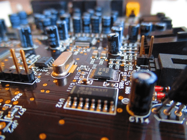
It’s sometimes called Aluminium Bases, Aluminiumclad or Metalclad (MC PCB), or thermally conductive PCB (all PCB is thermally conductive). When compared to the ordinary versions of R4 and R3, it is possible to get a thermal performance that is three to ten times better. One of the sides of the shot focuses on an MSPCB mounted on aluminum.
Insulation material is applied to the metal in the IM. As a result, the IMS PCB integrates metallic material, either as a thin layer or an inner layer, with the goal of enhancing the mechanical and thermal qualities of the board.
Additionally, they are famous for the metal core components and aluminum coatings that they use in their products. Standard printed circuit boards (PCBs) can be effectively replaced with a superior alternative in the form of a PCB that features metal cores.
The component is appropriate for use in situations in which the circuit requires high-density stability or in which the high temperature must be managed away from the LED and power components. Aluminum is used in the construction of IMS boards, which allows for superior heat conductivity. This makes IMS-compatible PCBs a more reliable device.
Why do IMS PCBs work?
- Temperatures like those seen in processing systems can cause poor circuit board functioning or even malfunction.
- The increase in potential thermal stresses increased dramatically through technological advancements.
- The present electronic circuit boards feature tightly stacked components in smaller forms.
- Effective cooling management of PCB heat is thus crucial to the prevention of total omissions of functions on devices.
- Using a MEMS-based circuit board will reduce the amount of heat that the circuit board can generate.
- The LED and the transistor produce high amounts of heat.
Applications of IMS PCBs
Insulating plastic substrates PCBs can serve a broad spectrum of applications. This increased thermal conductivity makes this board a dense pack and enables longer operation periods.
This makes them particularly useful for high-power systems. Automotive industry IMS PCB is used for the manufacture of automobile parts. In particular, you’ll see this with a light headlamp and a power steering system.
Due to their improved thermal conductivity, IMS boards can make excellent automotive component components. LEDs offer more energy distribution than conventional PCBs in the industry. It is possible to spread the heat generated from LED devices easily using IMS PCBs.
IMS Printed Circuit Boards are appropriate for a broad variety of applications, some of which include high-power, combustible, and high-temperature settings. They can function as ground layers, which safeguard delicate electronic components and directly absorb heat that is generated by surface-mount device (SMD) components.
These circuit boards are very helpful in the areas of light-emitting diodes (LEDs), solid-state relays, and power electronics. Nevertheless, they bring about a plethora of extra advantages. Read on if you’re not sure if IMS PCBs are the best option for your next project but would like to learn more about them and how they might be useful to you during the creation of your next endeavor.
One of the most frequently seen benefits of an IMS PCB is the superior thermal management it provides. For instance, a base metal that has outstanding thermal conductivity would be an excellent example of a good thermal conductor since it would reduce the amount of heat that needed to be conveyed.
These parameters will be used as a basis for the design and production of the board by the manufacturer, who will also adhere to them. One way to cut expenses is by utilizing a standard thickness. In order to prevent an unsafe level of heat accumulation, it is essential, however, to check that the material that will be used for the base metal has good thermal conductivity.
Copper, aluminum, and a variety of other metals are frequently utilized in the production of IMS-printed circuit boards. Copper is a material that is widely utilized in IMS PCBs due to the good thermal and electrical qualities that it possesses.
A copper layer is the most often used for substrates, although aluminum is the most popular and it is substantially less costly, copper layers are used for substrate material.
Because of its great electrical and thermal conductivity, aluminum is a highly desirable material for use in diverse contexts. Keep in mind, however, that aluminum has a significantly lower resistance to corrosion than other metals. These, amongst others, are important applications of IMS PCBs. Highlighted below are a few others:
LED Technology
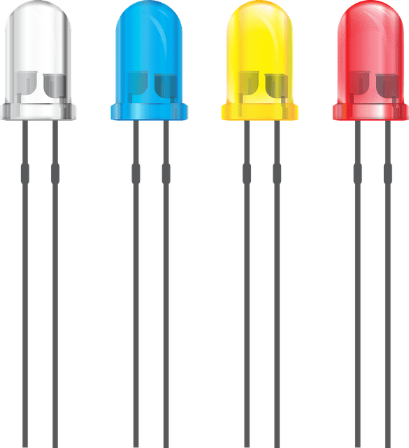
The LED circuits are getting smaller, more energy-efficient, and more power-dense as time goes on.
IMS-printed circuit boards are extensively used in LED circuits because of their ability to effectively absorb heat produced by LED surface mount devices (SMDs) and transmit that heat to a heatsink material.
Automotive industry
Control units(CU) for contemporary cars sometimes number in the dozens. These handheld computers are vulnerable to the high temperatures that can be found in or around the engine since they are installed there.
IMS-printed circuit boards deliver the required heat conductivity as well as the appropriate mechanical qualities for various applications.
Solid State Relays
The equivalent of mechanical relays in the current era is known as a solid state relay (SSR). These include a power switching device as well as a circuit that drives optocouplers (MOSFET or TRIAC).
Every component is crammed into a relatively compact case, which also serves as the heat sink for the entire assembly. These make use of IMS PCBs, which collect heat from all of the components and transport it to the enclosure so it may be dissipated.
Power Electronics
In electronic circuits, the power supply devices generate an excessive amount of heat. IMS PCBs are able to effectively distribute this heat despite the absence of discrete heatsinks for each component. Because of this, designs may be made more compact.
Thermal Management Process in IMS Circuit Boards
The board provides excellent thermal resilience because its thermal conductivity is excellent for PCBs IMS.
IMS PCBs also have thermal management capabilities. This PCB uses metal for base layering. Metals are very good heating conductors, and they are responsible for achieving high or low thermal resistance to IMS PCB. During the heat exchange, the thermal conductivity of thermoelectric material can be used for the exact measurements.
Similarly, examining the thermal conductivity of the components will help in understanding their thermal management and heat dissipation. A manufacturer has further to provide suitable materials at a location to prevent heat loss. Thermal conductivity in IMS boards contributes to thermal management.
Different Types of IMS Boards
Below Are Differences Observed in IMS-based PCBs for Industrial Application and Manufacturing Use
Aluminum metal substrate PCB
This metal is used for the metal substrate material more frequently than any other. Aluminum has moderate heat conductivity and electrical characteristics, in addition to being significantly more affordable than copper.
Copper metal substrate PCB
Copper, a material that is utilized as a substrate, is only employed in a few applications because of its good heat conductivity and excellent electrical conductivity. When compared to aluminum and stainless steel, copper possesses the most desirable material qualities.
The fact that copper is prone to corrosion is the most significant disadvantage of possessing it. And the cost of the material: copper substrate printed circuit boards may be rather pricey.
Stainless steel metal substrate PCB
In many applications, particularly those with a premium on mechanical strength, stainless steel is used as a substrate material. When compared to aluminum and copper, stainless steel’s electrical and thermal performance is worse, even though it is the least expensive option. It is significantly less expensive than aluminum and copper.
Based on the Printed Circuit Board Layer and Component Mounting Location, There Are Four Different Types of IMS PCBs

Two Layers With Single Component Mounting Side IMS PCBs
Due to the presence of two thick copper layers in this kind, it is possible to combine more complicated circuits. It is possible for the superior thermal conductivity to be lessened thanks to the presence of an FR4 layer that is in between two copper layers.
Heat transmitting vias are utilized because they provide superior thermal conductivity. Heat is transferred from the topside to the bottom substrate via these thermal vias, which touch the underside of the SMD components.
Dual Component Mounting Side IMS PCBs
This design has two solder mask layers, each of which can have components populated upon it. The metal substrate is located in the center of the structure. The transport of heat and current is accomplished by the use of via. In order to insulate the current-carrying vias, a substance similar to resin is put around the thermal vias.
Single-Sided Metal Core IMS PCBs
This specific variant of IMS PCBs only has one side that may be used for attaching components. One of the layers was composed of thick copper, while the bottom side was comprised of the metal substrate, which doubled as the heatsink for the device.
LED Printed Circuit Boards and Solid State Relay (SSR) Printed Circuit Boards are both examples of typical circuit configurations that use this kind.
The mechanical qualities of these PCBs have been improved. Because it is located in the middle, metal substrates offer less heat-sink qualities than other types, but they do allow for more intricate circuits.
Multilayer Dual Component Mounting Side IMS PCBs
The other configurations are easier to understand in comparison to this one. It contains numerous copper layers sandwiched on the top and bottom sides of the metal core, and it supports the mounting of components on both sides of the metal core PCB.
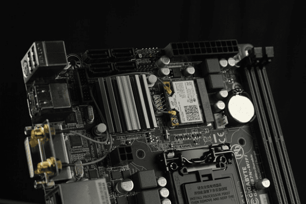
It can accommodate more complicated designs, such as single-board computers (SBC), in which the processor and all of the components are soldered onto a single, tiny PCB.
The metal core functions as a heat transferring vias, which allows for more even temperature distribution.
Differences Between IMS and FR4 PCBs
There are several different differences between FR4 and IMS FR3 PCB besides thermal conductivity and mechanical properties listed below.
- It is possible to use through-hole components with single-layer FR4 PCBs, however, this is not the case with IMS PCBs.
- When comparing PCBs of the same layer type, IMS boards often have better heat conductance values.
- Solder masks for IMS PCBs are normally white, but those for FR4 PCBs might be green, black, or amber.
- In IMS PCB production, the substrate material was cut with diamond-coated saw blades, while FR4 can be machined with standard equipment.
- While most IMS PCBs only have a single copper layer, FR4 PCBs may accommodate many. The complicated manufacturing process makes multilayer IMS PCBs unusual.
- In contrast to FR4 PCBs, which may be any thickness and sustain hundreds of layers, IMS PCBs have a thickness limit beyond which their advantages are nullified.
Conclusion
Now that we have covered what an IMS PCB is, its benefits, its uses, its thermal processes, and the many types of IMS boards, we can say that this article is complete. These electrical boards are essential components that play an important role in the efficient operation of linked appliances.
It is essential that you have a thorough comprehension of the intricacies and quirks that are associated with the procedures of the various boards and that you select the appropriate responses to their requirements.
