The L298N is a popular dual H-bridge motor driver integrated circuit (IC) that is widely used in robotics and other electronic projects. It is designed to control two DC motors or a single stepper motor, and is capable of driving currents of up to 2A per channel. The L298N is a versatile IC that can be used in a variety of applications, but its PCB layout is critical to its performance.
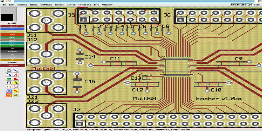
The PCB layout of the L298N is crucial to its performance, as it can affect the IC’s thermal management, electromagnetic interference (EMI) and noise immunity, and overall reliability. A well-designed PCB layout can improve the IC’s thermal management by reducing the thermal resistance between the IC and the PCB, which can help to dissipate heat more effectively. It can also improve the IC’s EMI and noise immunity by reducing the parasitic capacitance and inductance between the IC and the PCB, which can help to filter out unwanted noise and interference.

L298N PCB Layout Design Considerations
Designing a PCB layout for the L298N motor driver requires careful consideration of several factors. Here are some key design considerations to keep in mind when designing the layout:
-
Power Supply: The L298N requires a dual power supply (Vcc1 and Vcc2) for proper operation. It is important to ensure that the power supply can provide enough current to meet the requirements of the motor being driven.
-
Ground Planes: Proper grounding is critical for the L298N to operate correctly. It is recommended to use a ground plane on the PCB to ensure a low impedance ground path.
-
Thermal Dissipation: The L298N can generate a significant amount of heat, especially when driving high current motors. It is important to provide adequate thermal dissipation on the PCB to prevent overheating.
-
Component Placement: Proper component placement is crucial for the L298N to operate correctly. It is recommended to place the L298N chip as close to the power supply as possible to minimize voltage drop.
-
Trace Width: The trace width for the power and ground connections should be as wide as possible to minimize resistance and voltage drop.
-
Noise Reduction: The L298N is susceptible to noise, which can cause erratic motor behavior. It is recommended to use bypass capacitors and ferrite beads to reduce noise on the PCB.
-
Signal Integrity: The signal lines should be kept as short as possible to minimize signal degradation. It is also recommended to use a ground plane to reduce signal noise.
By keeping these design considerations in mind, you can create a reliable and efficient PCB layout for the L298N motor driver.
Power Supply Section

The L298N motor driver module requires a power supply of 5V to 35V DC. The power supply section of the PCB layout is crucial for the proper functioning of the motor driver module.
To ensure a stable power supply, it is recommended to use a separate power supply for the logic and motor power. The logic power supply should be connected to the 5V pin on the module, while the motor power supply should be connected to the VM pin.
The power supply section should include capacitors to filter out any noise or voltage spikes. A 100nF ceramic capacitor is recommended for the logic power supply, while a 1000uF electrolytic capacitor is recommended for the motor power supply.
It is also important to ensure proper grounding of the power supply section. The ground pins of the logic and motor power supplies should be connected to the ground plane of the PCB layout.
Overall, a well-designed power supply section is crucial for the proper functioning of the L298N motor driver module. Proper filtering and grounding can help reduce noise and voltage spikes, ensuring a stable power supply for the module.
Motor Driver Section
The motor driver section of the L298N PCB layout is an essential part of the board. It is responsible for driving the motors connected to the board. The L298N motor driver IC can handle up to 2 amps of current per channel and can control two DC motors or one stepper motor.
The motor driver section of the L298N PCB layout consists of two H-bridge circuits, one for each motor. Each H-bridge circuit is made up of four transistors, two NPN and two PNP, which are used to switch the direction of the current flowing through the motor. The direction of the current determines the direction of the motor rotation.
To control the motor driver section of the L298N PCB layout, the user needs to send signals to the input pins of the motor driver IC. The signals are used to control the direction and speed of the motor. The L298N motor driver IC has four input pins, two for each motor. By sending different combinations of signals to the input pins, the user can control the direction and speed of the motors.
Overall, the motor driver section of the L298N PCB layout is a crucial part of the board that allows users to control the direction and speed of the motors connected to the board. By understanding how the motor driver section works, users can design and build more complex projects that require precise motor control.
Control Section

The control section of the L298N PCB layout is responsible for controlling the direction and speed of the motor. It consists of several components, including resistors, capacitors, and diodes.
One of the key components in the control section is the H-bridge, which is responsible for controlling the direction of the motor. The H-bridge is made up of four transistors that are arranged in a specific way to allow current to flow in either direction through the motor.
To control the speed of the motor, the control section uses pulse-width modulation (PWM). PWM works by varying the duty cycle of a square wave signal to control the average voltage delivered to the motor. This allows for precise control of the motor speed.
In addition to the H-bridge and PWM control, the control section also includes a number of protection features, such as diodes that protect against reverse voltage and capacitors that filter out noise from the power supply.
Overall, the control section of the L298N PCB layout is a critical component that allows for precise control of the motor direction and speed. By using a combination of H-bridge control and PWM, the L298N is able to provide reliable and efficient motor control in a wide range of applications.

