The PCB assembly has been a topic of discussion for a while now. Every engineer who wants to manufacture their circuit boards must understand how it works before proceeding with their project. Having a flexible PCB assembly gives you the advantage of producing your boards conveniently. We can accurately use this kind of circuit board to fit into any space, whether large or small. But the rigid PCB assembly offers firm support to your circuit board. With the help of a flexible PCB, you can find more space for your components. There are a lot of advantages that one can get from this technology.
Flexible PCB Assembly
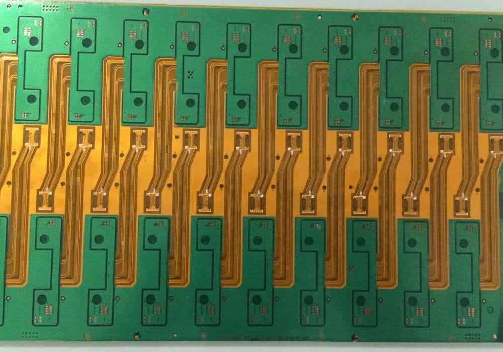
Flexible circuit boards are essential in making a wide range of electrical products. This type of PCB is flexible and thin enough to bend into any given shape. One can make them from both paper and plastic. Manufacturers place the components on the board’s surface. They use special soldering methods and certain chemicals. The bottom layers connect to the top layers by placing them together. They Seal them to ensure that the insides don’t disappear. The top layer connects to the other layers using conductive paste or plastic tape. They repeat the process until the board reaches its desired size.
To achieve the effect of a flexible PCB assembly optimally, one must follow specific steps carefully. The first step involved in the whole process is creating an accurate design on the board itself. A good design ensures that all circuits and components have the perfect space for proper function. Next, you should use only high-quality components. These are the parts that form a significant role in the functioning of your circuits. The design of your circuit and its components should be compatible with the flex PCB assembly. The last step is to have a proper testing procedure to ensure that your product functions appropriately before sending it to market.
The above steps concerning flexible PCB assembly may seem easy to follow, but specific problems might occur on the way. One of them is liquid solder residue after etching the board.
Step-by-step Manufacturing Process of Flex Circuit Boards
The flexible circuit board manufacturing process includes the following steps:
STEP 1: Flex PCB Build Up
Building up a flexible circuit board starts with creating printed circuit layouts. We manufacture the layout using different layers to create the traces and pads needed in the board outline. The material layers used during this process include flexible PCB sheets, conductive materials, and adhesive materials.
a) Looping:
This process creates traces on the material layers to result in the printed circuit layouts. These layouts include positive and negative pads used for soldering.
The first material layer used to create the flexible circuit is a standard-thickness FR4 material.
b) Sizing conductor:
While preparing the layout for the flexible PCBs, a person may choose to use a larger conductor size or a smaller conductor size. A person can also choose to use a particular material to determine the flexibility of their circuit boards. Examples include copper-clad or copper-clad laminates.
c) Etching:
The next step of the manufacturing process involves etching the flexible circuit boards. This is an essential process because it determines the quality of the printed circuit board. Etching consists in placing an electrical current on an oxidized metal plate. It helps to remove certain materials with a voltage difference.
d) Routing:
The next step of the manufacturing process is routing, creating tracks on the board. We create the track patterns with a thin layer of copper and cut them with a snip blade.
e) Ground Planes:
The proper manufacturing of flexible circuit boards requires creating ground planes. The ground planes reduce interference between the different tracks, pads, and traces on the board. This determines how well a PCB will work.
STEP 2: FPC Fabrication Process
The FPC boards creation process is similar to classic PCB manufacturing processes. We place the individual components on the flexible circuit boards’ surface using unique soldering methods and certain chemicals. The bottom layers connect to the top layers by placing them together. We seal them to ensure that the insides don’t disappear.
The top layer connects to the other layers using conductive paste or plastic tape. We repeat the process until the board reaches its desired size.
a) Size of the holes:
The first step of the manufacturing process is the determination of hole sizes. The hole sizes depend on the size of the components placed in the circuit board. The sizing must account for many factors, including the size of components, placement, and type of circuit we are using.
b) Filleting:
This step places small metal parts in the holes of the circuit boards. The parts must be of a size that will fit into the holes. If the part is too large, we can only place it after removing a masking tape layer.
c) The materials used during this step include silver nickel and nickel-plated iron.
d) Button plating:
In some cases, the circuit boards require a specific material that will help protect the component from corrosion. The materials used for this protection process include tin, copper, and gold.
The materials used during this step include a tin plate and a clear epoxy ink.
STEP 3: Concentrate on Physical Constraints
We determine the physical constraint of the flexible board by the positioning and shape of the components. How we glue two or more circuit board layers will also affect it. This process involves placing components in different positions and shapes to determine how a pattern will work. The materials used during this step include a laser printer, a flexible PCB, and an adhesive-backed hook and loop fastener.
The first step to creating a physical constraint is placing components in various spots on an adhesive-backed hook and loop fastener.
a) Adhesive-backed films:
This is a process of placing components on adhesive-backed film to determine how a particular layout will work. Check the placement and layout of each element before gluing the layers together.
b) Screen-printable liquid
We place screen-printable liquid overcoats on the components to determine how a particular layout works. The liquid overcoats must cover all the components and holes in the circuit board. The materials used during this step include epoxy black ink, epoxy clear ink, and an adhesive-backed hook and loop fastener.
c) Film polymers and photo imaginable liquid:
These two materials help determine how a particular layout will work during the physical constraint process. The materials used during this step include film polymers and photo imaginable liquid.
Rigid PCB assembly
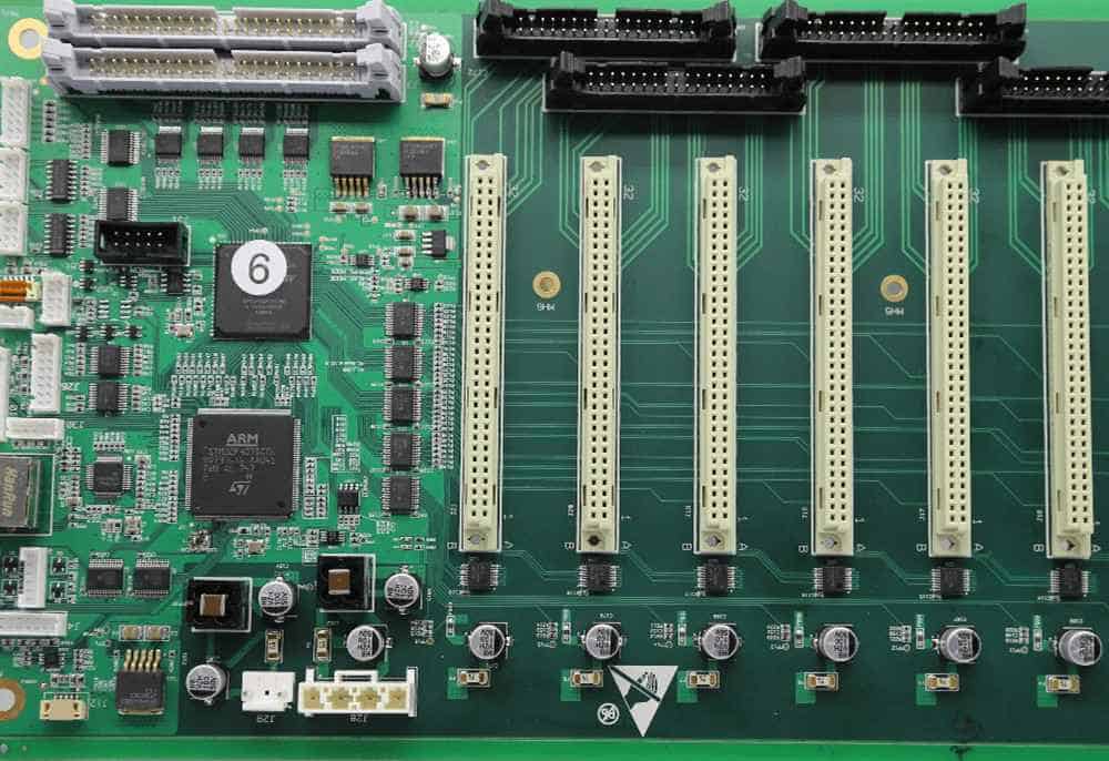
A rigid PCB usually has a metal backplane placed on the flexible PCB. The backplane material is then connected to the other layers and sealed at the edges to form a rigid PCB assembly. These assemblies are helpful in many applications. Examples include VGA boards and other consumer electronics products.
Rigid PCB Manufacturing Process
The rigid PCB manufacturing process includes several steps. They involve placing the components on flatbed scanners for digital data transfer and placing them on an adhesive-backed hook and loop fastener.
1. Material Preparation:
The first step of the rigid PCB manufacturing process involves placing the components on a flatbed scanner. We place the components on an adhesive-backed hook and loop fastener.
2. Exposure of Circuit Pattern:
The next step of the rigid PCB manufacturing process involves exposure to create circuit patterns on the base. The base has a transparent material layer on top of it that allows light to penetrate it. We make the pattern by drying chemicals onto the base. The materials used during this step include epoxy black ink, clear epoxy ink, and a standard base coated with varnish.
3. Etching:
This process creates a circuit pattern by removing components on top of the base. After the exposing process, we apply an etching solution over the base. The etchant will eat away at the exposed areas of the base and leave it with a circuit pattern. The materials used during this step include an etch solution and soda ash.
4. Drilling:
During this step, we electrically connect and seal the components. We etch the circuit pattern into the base material, and a drilling tool helps make a hole for a wire or cable. The materials used during this step include an adhesive that we can adhere to the base, epoxy black ink, and clear epoxy ink.
5. Copper Plating:
This process involves placing the backplane on the base and applying nickel-plated copper around the edges. The materials used during this step include a clear epoxy ink and a standard base coated with varnish.
6. Coverlay Application:
This process involves placing a thin layer of plastic between the base and backplane. The plastic layer adheres to both materials. The materials used during this step include an adhesive-backed film, epoxy black ink, and clear epoxy ink.
7. Coverlay Lamination:
This step involves placing the coverlay over the backplane and laminating the materials together. The materials used during this step include a vinyl sheet and epoxy black ink.
8. Stiffener Application:
We create the circuit pattern on the coverlay and place a stiffener on top to make the rigid PCB. The materials used during this step include a stiffener and epoxy black ink.
9. Mounting:
We place the stiffener on the base and the PCB over it. The materials used during this step include a clear epoxy ink, a standard base coated with varnish, a stiffener, and an adhesive-backed film.
10. Testing:
After putting the LCD on the PCB, we test it to see it operational. The materials used during this step include an LCD, a custom backplane, and a standard base coated with varnish.
Flexible PCB assembly Vs. Rigid PCB assembly
Rigid PCBs and flexible PCBs fulfill the same essential function. However, there are many differences in their assembly methods. The rigid PCB assembly process uses a mechanized tool to place the components on an adhesive-backed hook and loop fastener. Flexible PCBs are much more complicated than rigid circuit board as we must assemble them by hand. Unlike rigid PCBs, flexible PCB assemblies do not use a fixed backplane and have various substrate materials.
1. Manufacturing Process
People can manufacture rigid PCBs using a mechanized process. The rigid PCB assembly process involves several steps. They include placing components on an adhesive-backed hook and loop fastener. The following step is exposure, etching, drilling, and plating. After this step is complete, we place the backplane on the flexible PCB and solder electrical wires. The materials used during this step include an adhesive that we can adhere to the base, epoxy black ink, and clear epoxy ink.
2. Material
We generally make Rigid PCB materials from copper and plastic. We can make flexible PCB materials from various materials, such as glass, semiconductors, and other metals. The flexible PCB assembly process involves exposing the components on the substrate. It also involves etching the substrate’s circuit pattern and drilling holes for wires or cables. The final step involves applying for a metal plate over the backplane to complete the assembly. We place the metal backplane on the flexible PCB and solder electrical wires.
3. Durability
The rigid PCB process is more durable than flexible PCBs because it uses a fixed backplane. It leaves less room for the different materials to bend and distort. Rigid PCBs are also much sturdier. This is because they can support heavier components and include mechanical components. They include gears and joints to provide additional support. On the other hand, flexible PCB assembly does not require any mechanical parts. It only requires adhesives to hold the different pieces together.
4. Weight
We usually make Rigid PCBs from copper and plastic. It makes them much heavier than flexible PCB material, which we generally make from glass and other metals. Rigid PCB assembly can weigh up to 25 pounds. Because we make flexible PCBs from lightweight materials, they are easier to transport.
5. Price
Rigid PCB assembly is much more expensive than flexible PCB assembly. It requires a mechanized manufacturing tool and a large factory space to complete the process. On the other hand, we can complete flexible PCB assembly in small factories that do not cost much to rent or purchase. Flexible PCBs are also much more cost-effective. We can use less expensive materials and require no mechanized tools to complete the process.
6. Electrical Components
Rigid PCBs can only have fixed components that we attach to a backplane. At the same time, flexible PCB assembly allows for the use of various electrical components attached directly on top of the substrate. Wafer-level packaging (WLP) sometimes also called chip scale packaging (CSP) or 3-D IC (3-D ICS. It is a technology that helps connect the active die of a semiconductor device to a substrate. We can do this packaging at the wafer level before packaging the individual dies into separate components. Wafer-level packaging requires much less processing than traditional methods. This is because it eliminates many steps used in multichip module assembly.
7. Resistance
The components are rigidly attached to a backplane in rigid PCB assembly and cannot move or shift. Flexible PCB assembly uses an exposed substrate, leaving the components vulnerable to distortion. This is because we do not hold the components in place, except by rigid adhesives used to hold them in place.
8. Environmental Compatibility
Because rigid PCBs have fixed components that cannot move, they can be more environmentally friendly than flexible PCBs. Since we make them from copper and plastic and are heavier than flexible PCB material, we can recycle the rigid PCBs at the end of their life. This is because they can serve as raw materials for other manufacturing processes or reuse.
9. Sophistication of Design
Rigid PCB assembly is more sophisticated than flexible PCBs. It is because it incorporates fixed components and cannot bend. We cannot change the design of rigid PCBs once we manufacture them. Then, we can modify circuits on a flexible PCB before placing them on the substrate. We can also do it after putting them on the substrate, making them more sophisticated.
When to use rigid PCB and when to use flexible PCB
Different projects need different kinds of PCBs to perform their function. This is because rigid PCB assembly allows for more advanced circuits and provides more durable components. Flexible PCB assembly uses a system that leaves the components vulnerable to deformation, and we cannot change it once made. Flexible PCBs are much cheaper than rigid PCBs, ideal for manufacturing small products, such as children’s toys. Rigid PCBs help the defense industry and other advanced industries that need sophisticated electronic products.
When to use rigid PCB
We use Rigid PCBs when the product’s structure is not as important as its functionality. For example, we would use flexible PCB assembly when creating a computer because there are no critical parts inside the computer that need to bend or rotate. We would use rigid PCB assembly when making a camera because sensitive parts require safety measures against breaking or damage.
There are several other projects in which we would use rigid PCBs. They include military and aerospace applications, where the components need to be precise and precise. We would use Rigid PCB assembly when designing a vehicle, such as a jet or an airplane. This is because rigid PCBs are more lightweight and reliable than flexible PCBs. Because rigid PCBs are much more durable, we can use them to expose the components to outside elements. They include a vehicle or camera used outside the factory environment.
When to use flexible PCB
Flexible PCBs are essential when we need flexibility beyond what rigid PCB assembly can offer. When creating an electronic toy for children, flexible PCB assembly is ideal. It can create the toy with a simplified design that can fit into a child’s hands and function well. We can easily replace the parts inside the toy when they break. Because flexible PCB assembly is less expensive than rigid PCB assembly, it is ideal for small businesses and start-ups that might not have a lot of capital to invest in specialized equipment.
Flexible PCB assembly is also perfect for projects that only need a few dozen units of each product. It allows the production of these products without requiring significant investments in specialized equipment. However, much of the specific use and advantages of rigid (rigid) versus flexible PCBs are common, so it is helpful to know both. Since reducing PCB complexity and increasing flexibility is a trend in PCB design today, it is essential to know what each offers.
The construction of a flexible PCB differs from the rigid type because it reduces the number of layers required by the flex circuit assembly.
IPC Standards for Rigid and Flexible PCBs
When choosing rigid PCB assembly or flexible PCB assembly, one thing to consider is the standards available to ensure that all the components in the circuit are compatible.
Generic Standard on Printed Board Design (IPC-2221A)
The IPC-2221A is a generic standard on printed board design. It is not specific to rigid or flexible circuit boards, and we use it with other forms of PCB assembly such as hybrid and single-sided PCBs. The standard includes information on designing the layout of circuit boards and addresses other essential issues in printed circuit board design.
Sectional Design Standard (IPC-2223)
The IPC-2223 standard was a more specific version of the IPC-2221A standard. We use it with rigid circuit boards only, and we use it to describe the layout of a single printed board. The standard includes information on the components that we should place in some areas on the board to be easily accessed, identified, and replaced.
Specification for Base Materials (IPC-4101)
The IPC-4101 standard helps specify the materials, such as chemicals, that we use to make rigid and multilayer PCBs. The standard includes instructions on processing the material and testing the finished product properly.
Flexible Base Dielectrics (IPC-4202)
The IPC-4202 is a set of design guidelines to make flexible printed circuit boards. The standard includes basic materials and the general design of a flexible PCB’s layout. In addition, there are requirements for the efficiency of the components and information on how to test them properly.
Adhesive Coated Dielectric Films (IPC-4203)
The IPC-4203 standard helps specify the types of materials and their characteristics to construct flexible printed circuit boards. The standard specifies how we should electrically test the components. It also includes information on manufacturing the boards with a flexible adhesive.
Flexible Metal-Clad Dielectrics (IPC-4204)
The IPC-4204 standard is a set of design guidelines for metal-clad printed circuit boards used to manufacture flexible circuits. The standard includes instructions for using a thin aluminum layer in the circuit board to ensure its flexibility, and it specifies how to build and test the finished product.
Qualification and Performance Specification for Flexible Printed Wiring (IPC-6013)
The IPC-6013 standard defines the performance and quality requirements needed to manufacture flexible printed wiring.
The standard also requires the manufacturer to have a system to ensure enough testing on each board. The purpose is to ensure that the finished product will be compatible with other components in the circuit to function properly. The manufacturer must also have a system for tracking defective boards and ensuring their proper disposal.
Conclusion
When it comes to PCBs and their assembly, the rigid and the flexible make a big difference. This debate started years ago between engineers on whether to go for the rigid or flexible PCB assembly. Having a flexible PCB gives you more space while using it in a certain space. This is one of the key advantages used in different industries such as automobiles, satellite communication systems, aerospace, etc. But rigid PCB is more prevalent among manufacturers because it offers more stability for your circuit board.
The placement of components is more precise and accurate with a rigid PCB assembly. But flexible PCB assembly also has advantages, such as adding new components without sacrificing space for other ones. Flexible PCB assembly allows you the creative freedom to design your circuit boards as per your needs and specifications. Considering all this, both the rigid and the flexible PCB assemblies are great options to choose from.
