A layout PCB compressor limiter is a type of audio processing device that is used to control the dynamic range of audio signals. This device is commonly used in recording studios and live sound applications to prevent audio signals from becoming too loud or distorted. The compressor limiter works by reducing the volume of the audio signal when it exceeds a certain threshold level.
One of the primary benefits of using a layout PCB compressor limiter is that it can help to create a more even and consistent sound. By controlling the dynamic range of the audio signal, the compressor limiter can help to prevent sudden spikes in volume that can be unpleasant to listen to. This can be especially important in live sound applications, where unexpected changes in volume can be disruptive to the audience.
Another advantage of using a layout PCB compressor limiter is that it can help to protect the speakers and other audio equipment from damage. By preventing the audio signal from becoming too loud, the compressor limiter can reduce the risk of distortion or clipping, which can cause speakers to blow out or other equipment to fail. Overall, the compressor limiter is an essential tool for any audio professional looking to create a high-quality sound that is both consistent and safe for their equipment.

PCB Layout
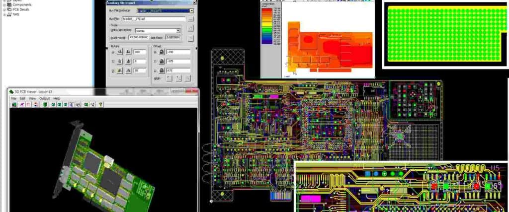
When designing a PCB for a compressor limiter, it is important to pay attention to the layout to ensure that the circuit functions properly. The layout should be optimized for signal integrity, noise reduction, and ease of assembly.
Components Placement
The placement of components on the PCB is critical for the circuit’s performance. The components should be placed in a way that minimizes the length of the signal paths and reduces the chances of crosstalk and interference.
It is also important to group components according to their functions. For example, resistors and capacitors that are part of a filter circuit should be placed close together to minimize the length of the signal path.
Routing
Routing is the process of connecting the components on the PCB with traces. The traces should be routed in a way that minimizes the length of the signal path and reduces the chances of crosstalk and interference.
The traces should also be wide enough to handle the current and voltage levels of the circuit. The width of the traces should be calculated based on the current and voltage levels of the circuit.
In addition, the traces should be routed in a way that makes it easy to assemble the PCB. This means that the traces should be routed in a way that allows for easy access to the components during assembly.
Overall, the PCB layout is an important aspect of designing a compressor limiter circuit. The components should be placed and routed in a way that minimizes the length of the signal path, reduces the chances of crosstalk and interference, and makes it easy to assemble the PCB.
Compressor Circuit

Working Principle
The compressor circuit is an essential part of a PCB layout for a compressor limiter. It works by reducing the dynamic range of an audio signal by attenuating the louder parts and amplifying the quieter parts. This results in a more even and consistent sound output.
The working principle of a compressor circuit can be explained through the use of threshold, ratio, attack, and release controls. The threshold control sets the level at which the compressor begins to reduce the gain of the audio signal. The ratio control sets the amount of gain reduction that occurs once the threshold is reached. The attack control sets the time it takes for the compressor to begin reducing the gain, and the release control sets the time it takes for the compressor to stop reducing the gain.
Types
There are various types of compressor circuits available for PCB layouts, including optical, FET, and VCA compressors.
Optical compressors use a light source and a photoresistor to control the gain reduction. The brighter the light, the less the gain reduction, and vice versa. This type of compressor is known for its smooth and natural sound.
FET compressors use field-effect transistors to control the gain reduction. They are known for their fast attack times and aggressive sound.
VCA compressors use voltage-controlled amplifiers to control the gain reduction. They are known for their versatility and ability to produce transparent sound.
Choosing the right type of compressor circuit for a compressor limiter depends on the desired sound output and the specific application.
Limiter Circuit
Working Principle
The limiter circuit is an essential part of the compressor limiter PCB layout. It is responsible for controlling the maximum level of the audio signal, preventing it from exceeding a certain threshold. The limiter circuit works by comparing the input signal to a reference voltage. If the input signal exceeds the threshold, the limiter circuit reduces the gain of the signal to prevent it from going over the limit.
Types
There are two main types of limiter circuits: hard and soft. Hard limiters are designed to completely stop the signal from going over the limit, resulting in a harsh, clipped sound. Soft limiters, on the other hand, gradually reduce the gain of the signal, resulting in a smoother, more natural sound.
Hard limiters are often used in applications where a very specific level needs to be maintained, such as in broadcasting or live sound reinforcement. Soft limiters are more commonly used in music production and recording, where a more natural sound is desired.
In addition to hard and soft limiters, there are also peak limiters, which are designed to prevent brief spikes in the signal from exceeding the limit. Peak limiters are often used in conjunction with other types of limiters to provide additional protection against sudden, unexpected changes in the audio signal.

