Line follower robots are becoming increasingly popular in the field of robotics. These robots are designed to follow a specific path, usually a black line on a white surface, using sensors and programming. One of the most important components of a line follower robot is the PCB layout.
The PCB layout of a line follower robot is crucial to its functionality. It determines how the various components of the robot are connected and how they communicate with each other. A well-designed PCB layout can ensure that the robot operates smoothly and accurately, while a poorly designed layout can lead to errors and malfunctions. Therefore, it is important to pay close attention to the PCB layout when designing a line follower robot.
Fundamentals
When designing a PCB layout for a line follower robot, it is important to understand the fundamentals of the robot’s operation. A line follower robot is a type of mobile robot that follows a line or path on the ground using sensors. The sensors detect the contrast between the line and the surface of the ground, allowing the robot to follow the line.
The PCB layout for a line follower robot should include the necessary components for the robot’s sensors, motor drivers, and microcontroller. The sensors used in a line follower robot are typically infrared sensors that detect the contrast between the line and the ground. The motor drivers control the speed and direction of the robot’s motors, while the microcontroller processes the sensor data and controls the motor drivers.
When designing the PCB layout, it is important to consider the power requirements of the robot. The motors used in a line follower robot can draw a significant amount of current, so it is important to include a power supply that can handle the load. Additionally, the PCB layout should include voltage regulators to ensure that the microcontroller and other components receive a stable power supply.
Overall, when designing a PCB layout for a line follower robot, it is important to consider the fundamentals of the robot’s operation and the power requirements of the components. By designing a well-thought-out PCB layout, you can ensure that your line follower robot operates smoothly and reliably.
Components

When designing a PCB layout for a line follower robot, it’s important to consider the components that will be needed. Here are some of the key components that should be included in the layout:
Microcontroller
The microcontroller is the brain of the line follower robot. It’s responsible for controlling the motors, reading the sensors, and making decisions about how to navigate the course. Some popular microcontrollers for line follower robots include the Arduino Uno, the PICAXE, and the Raspberry Pi.
Motor Driver
The motor driver is what allows the microcontroller to control the motors. It takes the signals from the microcontroller and converts them into the appropriate voltage and current to drive the motors. There are many different types of motor drivers available, but some popular choices for line follower robots include the L293D and the L298N.
Sensors
The sensors are what allow the line follower robot to “see” the course and make decisions about how to navigate it. The most common type of sensor for line follower robots is the infrared sensor. These sensors detect the contrast between the black line and the white background and send signals to the microcontroller to adjust the robot’s course. Other sensors that can be used include ultrasonic sensors and color sensors.
Power Supply
The power supply is what provides the voltage and current needed to run the motors, microcontroller, and other components. The power supply should be chosen based on the voltage and current requirements of the components being used. Some popular choices for line follower robots include 9V batteries, AA batteries, and rechargeable lithium-ion batteries.
In summary, when designing a PCB layout for a line follower robot, it’s important to consider the microcontroller, motor driver, sensors, and power supply. By carefully selecting and integrating these components, you can create a robot that is capable of navigating the course with precision and accuracy.
PCB Design
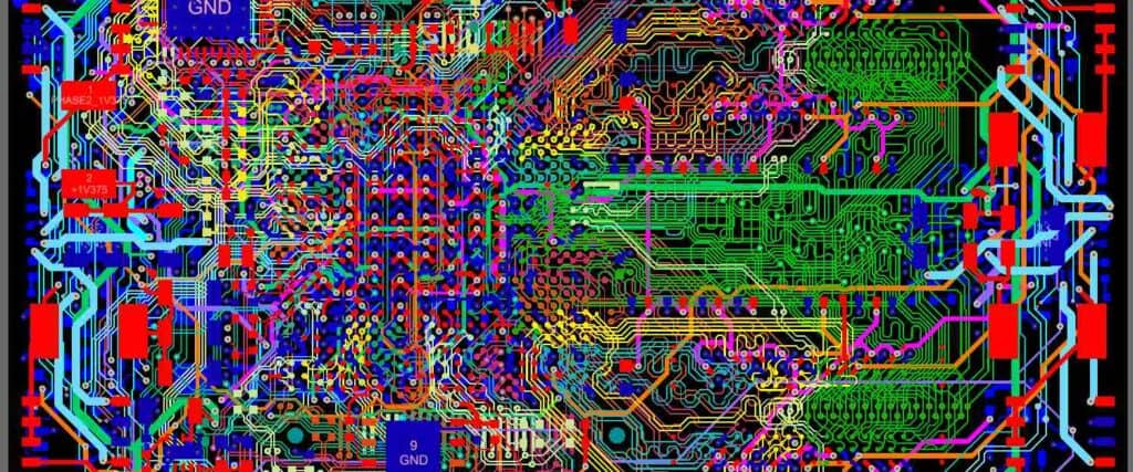
PCB design is one of the most crucial steps in building a line follower robot. The layout of the PCB determines the overall functionality and performance of the robot. A well-designed PCB can significantly improve the accuracy and speed of the robot.
When designing a PCB for a line follower robot, there are several factors to consider. The first and foremost is the size of the PCB. It should be compact enough to fit inside the robot chassis while providing enough space for all the necessary components.
Another important factor is the placement of the components on the PCB. The placement should be such that it minimizes the length of the traces between the components, which reduces the chances of signal interference and noise.
The traces on the PCB should be designed to minimize the resistance and capacitance, which can affect the performance of the robot. The width of the traces should be proportional to the current flowing through them.
In addition, it is essential to use the right materials for the PCB. The material should be able to handle the heat generated by the components and should have a low coefficient of thermal expansion to prevent warping.
Overall, designing a PCB for a line follower robot requires careful planning and attention to detail. A well-designed PCB can significantly improve the performance and accuracy of the robot.
Testing
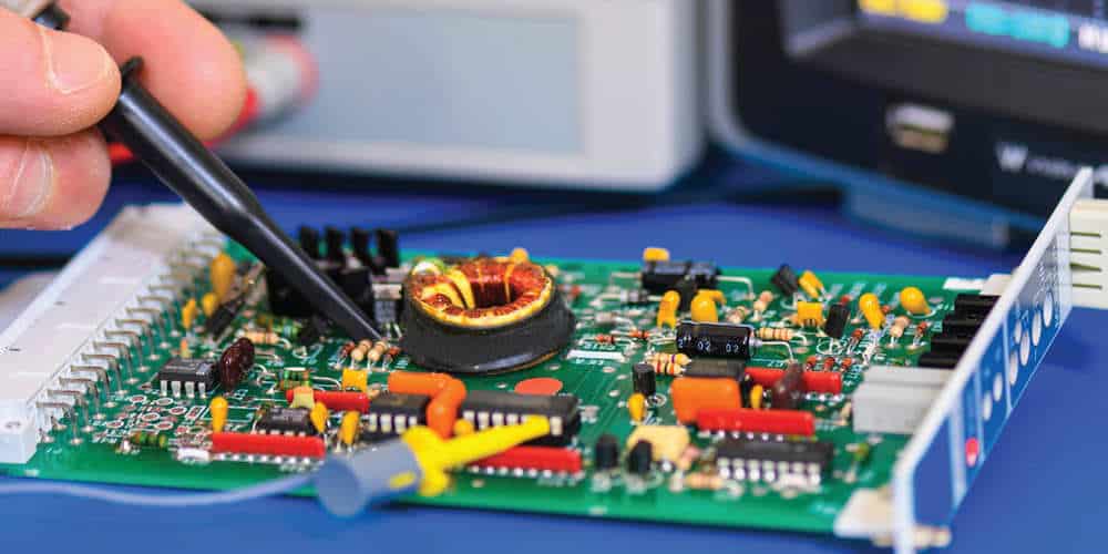
Once the PCB layout is complete, the next step is to test the line follower robot. Testing is an essential part of the development process, and it ensures that the robot functions as intended.
Before testing, it is essential to check the connections and ensure that there are no shorts or open circuits. A multimeter can be used to check the connections and ensure that they are correct.
Once the connections are verified, the robot can be powered on and tested. The robot should move forward when the sensors detect a black line and stop when they detect a white surface. If the robot does not function correctly, the problem can be identified by checking the connections and the code.
It is also essential to test the robot in different lighting conditions and on different surfaces to ensure that it works correctly in all situations. The robot should be able to follow the line accurately, even in low light conditions.
In conclusion, testing is an essential part of developing a line follower robot. It ensures that the robot functions correctly and can follow the line accurately. By following the testing process, any issues can be identified and resolved quickly, resulting in a functional and reliable robot.
