Millimeter wave technology is rapidly gaining popularity in the field of wireless communication. The technology, which uses frequencies between 30 and 300 GHz, offers several advantages such as high bandwidth and low latency. However, designing power amplifiers for millimeter wave frequencies is a challenging task due to the unique characteristics of the technology.
One of the most important components in millimeter wave communication systems is the power amplifier. Power amplifiers are responsible for boosting the signal strength, which is essential for long-range communication. However, designing power amplifiers for millimeter wave frequencies is not an easy task. The high frequencies involved require specialized techniques and components, and the design process is highly complex. In recent years, Gallium Nitride (GaN) technology has emerged as a promising solution for millimeter wave power amplifier design. GaN-based power amplifiers offer several advantages over traditional technologies, including higher efficiency, higher power density, and higher linearity.
Design Considerations
Frequency Range
When designing a millimeter wave GaN power amplifier, one of the primary considerations is the frequency range. Typically, these amplifiers are designed to operate in the frequency range of 30 GHz to 110 GHz. The choice of frequency range is largely determined by the application requirements. For example, radar systems often require amplifiers that operate in the 77 GHz to 81 GHz range, while communication systems may require amplifiers that operate in the 28 GHz to 39 GHz range.
Output Power
Another important consideration in the design of millimeter wave GaN power amplifiers is the output power. The output power requirements are determined by the application, and can range from a few watts to several hundred watts. In addition to the output power, the amplifier must also be designed to handle the required peak power levels. This is particularly important in radar applications, where the peak power levels can be very high.
Efficiency
Efficiency is a critical consideration in the design of millimeter wave GaN power amplifiers. These amplifiers are typically used in applications where power consumption is a concern, such as portable communication systems. The efficiency of the amplifier is determined by a number of factors, including the choice of transistor technology, the design of the matching networks, and the choice of biasing scheme. In general, GaN transistors offer higher efficiency than other transistor technologies, but they can be more difficult to design with.
In conclusion, when designing a millimeter wave GaN power amplifier, the frequency range, output power, and efficiency are the primary considerations. By carefully considering these factors, designers can create amplifiers that meet the requirements of a wide range of applications.
Circuit Topology
Class of Operation
The millimeter-wave GaN power amplifier design can operate in different classes of operation, such as Class A, Class AB, Class B, Class C, and Class F. The choice of the class of operation depends on the desired output power, efficiency, linearity, and bandwidth. Class A is the most linear but the least efficient, while Class F is the most efficient but the least linear. The designer needs to balance the trade-offs between these parameters to achieve the desired performance.
Matching Network
The matching network is a critical part of the millimeter-wave GaN power amplifier design. It is used to match the impedance of the amplifier to the load and the source. The matching network can be implemented using lumped or distributed elements. Lumped elements are suitable for narrowband applications, while distributed elements are suitable for broadband applications. The designer needs to optimize the matching network to achieve maximum power transfer and minimize reflections.
Biasing
The biasing of the millimeter-wave GaN power amplifier is crucial for achieving the desired performance. The biasing circuit provides the necessary DC bias voltage and current to the amplifier. The designer needs to ensure that the biasing circuit is stable and does not introduce any unwanted noise or distortion. The biasing circuit can be implemented using a variety of techniques, such as fixed bias, self-bias, and temperature-compensated bias.
In summary, the millimeter-wave GaN power amplifier design requires careful consideration of the class of operation, matching network, and biasing circuit to achieve the desired performance. The designer needs to optimize these parameters to achieve the desired power, efficiency, linearity, and bandwidth.
Simulation and Analysis

Modeling and Simulation Tools
The design of millimeter-wave GaN power amplifiers requires accurate modeling and simulation tools to predict the device performance. Various simulation tools like Keysight’s Advanced Design System (ADS), Microwave Office, and CST Microwave Studio are widely used for this purpose. These tools provide the capability to simulate the device behavior under different operating conditions and optimize the design parameters.
Load Pull Analysis
Load pull analysis is an important technique used in the design of millimeter-wave GaN power amplifiers. It involves varying the load impedance and measuring the output power and efficiency of the device to determine the optimum load impedance for maximum power and efficiency. Load pull analysis helps to optimize the matching circuit and achieve the desired performance.
Thermal Analysis
Thermal management is crucial in the design of millimeter-wave GaN power amplifiers as they generate a significant amount of heat. Thermal analysis helps to predict the temperature distribution and thermal behavior of the device under different operating conditions. It helps to optimize the heat sink design and cooling mechanism to ensure reliable operation.
In summary, accurate modeling and simulation tools, load pull analysis, and thermal analysis are essential in the design of millimeter-wave GaN power amplifiers to achieve the desired performance and reliability.
Fabrication and Testing
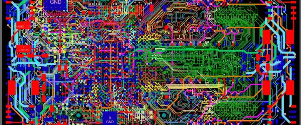
PCB Layout and Assembly
The PCB layout and assembly process plays a crucial role in the performance of millimeter wave GaN power amplifiers. The layout should be optimized to minimize parasitic inductance, capacitance, and resistance. The assembly should be done carefully to avoid any damage to the components and to ensure good thermal contact between the GaN transistor and the heat sink.
The PCB layout should be designed using electromagnetic simulation tools to optimize the transmission line width, spacing, and impedance. The vias should be placed strategically to minimize the inductance and resistance. The input and output matching networks should be designed to provide the desired impedance transformation and frequency response.
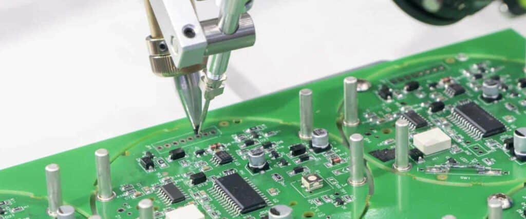
The assembly process should be done using a reflow oven with a temperature profile that is suitable for the components used. The GaN transistor should be mounted on a copper heat sink using a thermal interface material that provides good thermal conductivity and mechanical stability. The input and output matching networks should be tuned using a vector network analyzer (VNA) to achieve the desired frequency response.
Measurement Setup
The measurement setup for millimeter wave GaN power amplifiers should be designed to provide accurate and repeatable measurements. The setup should include a VNA, a power meter, and a spectrum analyzer. The VNA should be calibrated using a calibration kit that is suitable for the frequency range of interest. The power meter should be calibrated using a power sensor that is suitable for the power level of interest. The spectrum analyzer should be calibrated using a reference signal that is traceable to a national standard.
The measurement setup should also include a thermal chamber or a temperature-controlled environment to ensure that the measurements are done at a consistent temperature. The thermal chamber should be calibrated using a temperature sensor that is traceable to a national standard.
Performance Testing
The performance of millimeter wave GaN power amplifiers should be tested under various conditions to evaluate their suitability for different applications. The tests should include input and output return loss, gain, output power, efficiency, and linearity. The tests should be done over a range of frequencies, temperatures, and input power levels.
The input and output return loss should be measured using a VNA to ensure that the amplifier is properly matched to the source and load. The gain should be measured using a power meter to determine the amplification factor of the amplifier. The output power and efficiency should be measured using a power meter to determine the power output and efficiency of the amplifier. The linearity should be measured using a spectrum analyzer to determine the intermodulation distortion (IMD) and third-order intercept point (IP3) of the amplifier.
Overall, the fabrication and testing of millimeter wave GaN power amplifiers requires careful attention to detail and a thorough understanding of the design principles. By following best practices and using appropriate measurement techniques, it is possible to achieve high-performance amplifiers that are suitable for a wide range of applications.
