Perfboard design is an important aspect of electronics engineering. Perfboard, also known as a prototyping board or a breadboard, is a board used for creating electronic circuits. It is a cost-effective and efficient way to design and test circuits before they are implemented on a printed circuit board (PCB).
Perfboard design is a complex process that involves many factors, such as the size of the board, the number of components, and the layout of the circuit. The design process requires careful consideration of these factors to ensure that the circuit functions properly and efficiently. There are many resources available for learning perfboard design, including online tutorials, books, and courses. By mastering the art of perfboard design, engineers can create functional and reliable circuits that meet the needs of their projects.
Basics of Perfboard Design
What is Perfboard Design?
Perfboard design is a method of creating electronic circuits on a perforated board. It is an affordable and flexible way to create custom circuits for hobbyists and professionals alike. Perfboard is made up of a grid of holes that are connected by metal traces. These traces allow you to solder components onto the board and create a circuit.
Types of Perfboard
There are two main types of perfboard: stripboard and prototyping board. Stripboard has pre-made copper strips that run the length of the board, making it easier to connect components. Prototyping board, on the other hand, has a grid of holes that you must manually connect with wire to create a circuit.
Tools and Materials Required
To create a perfboard design, you will need a few basic tools and materials. These include:
- Perfboard (stripboard or prototyping board)
- Soldering iron and solder
- Wire cutters and strippers
- Components (resistors, capacitors, diodes, etc.)
- Printed circuit board (PCB) layout or schematic diagram
It is important to have a clear idea of the circuit you want to create before starting the perfboard design. This will help you choose the appropriate components and layout for your board.
In summary, perfboard design is a cost-effective and versatile way to create custom electronic circuits. With the right tools and materials, anyone can create a functional circuit on a perfboard.
Designing a Perfboard Circuit

Schematic Design
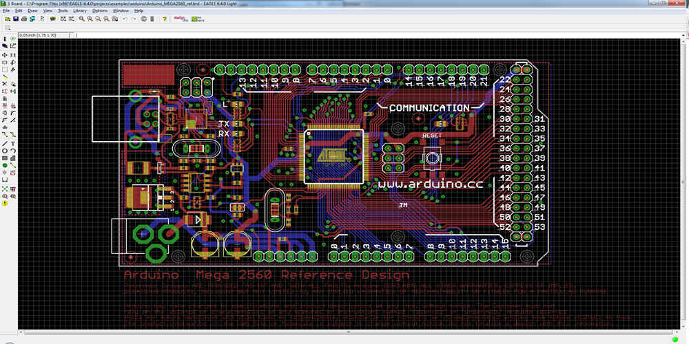
Before starting the perfboard design, it is important to create a schematic diagram of the circuit. The schematic will help in understanding the connections between the components and ensure that the circuit works as intended. It is recommended to use a software tool to create the schematic, as it can save time and make the process more efficient.
Layout Design
Once the schematic is complete, the next step is to design the layout of the perfboard. The layout should be based on the schematic and should take into account the physical dimensions of the perfboard. It is important to ensure that the layout is neat and organized, as this will make it easier to troubleshoot any issues that may arise.
Component Placement
After the layout is complete, the next step is to place the components on the perfboard. It is important to ensure that the components are placed in the correct locations, as this will affect the functionality of the circuit. It is recommended to start with the smallest components and work towards the larger ones, as this will make it easier to fit everything on the perfboard.
In summary, designing a perfboard circuit involves creating a schematic, designing the layout, and placing the components. By following these steps and paying attention to detail, you can create a functional and efficient perfboard circuit.
Soldering Techniques
Through-Hole Soldering
Through-hole soldering involves inserting the leads of components through holes in a perfboard and then soldering them to the copper pads on the other side. This technique is commonly used for larger components that cannot be surface-mounted.
To ensure a strong and reliable connection, it is important to follow these steps:
- Place the component in the correct hole and bend the leads to hold it in place.
- Apply heat to the pad and lead simultaneously with a soldering iron until the solder melts and flows around the lead.
- Remove the heat and allow the solder to cool and solidify before moving the board.
It is important to avoid overheating the component or pad, as this can damage the board or cause the component to fail.
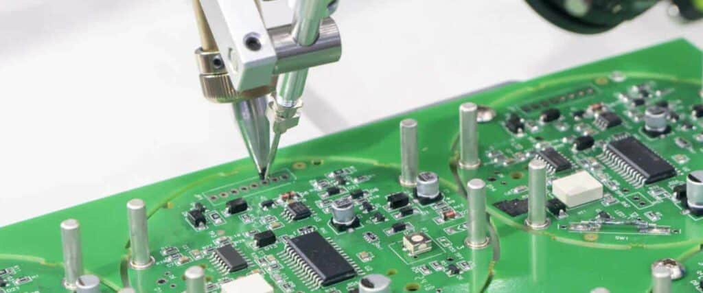
Surface Mount Soldering
Surface mount soldering involves attaching components to the surface of a perfboard using small pads and solder paste. This technique is commonly used for smaller components and allows for more compact designs.
To ensure a strong and reliable connection, it is important to follow these steps:
- Apply a small amount of solder paste to the pad where the component will be placed.
- Place the component on the pad and apply heat to the pad and component simultaneously with a hot air gun until the solder melts and flows around the component.
- Remove the heat and allow the solder to cool and solidify before moving the board.
It is important to avoid applying too much solder paste or overheating the component, as this can cause solder bridges or damage the component.
By following these techniques, you can ensure a strong and reliable connection between your components and perfboard.
Testing and Troubleshooting
Testing the Circuit
Before connecting the circuit to a power source, it is recommended to perform a continuity test using a multimeter to verify that there are no shorts or open circuits on the perfboard. Once the circuit is powered up, it is important to check the voltages at various points of the circuit using a voltmeter. This will help to ensure that the circuit is functioning as expected and that the components are receiving the correct voltages.
Troubleshooting Common Issues
If the circuit is not functioning as expected, there are a few common issues that could be the cause:
-
Short circuits: Check for any solder bridges or wires that may be touching each other where they shouldn’t be.
-
Open circuits: Check for any broken or disconnected wires or components.
-
Incorrect component orientation: Double-check that all components are installed in the correct orientation.
-
Incorrect component values: Verify that all components are the correct values as specified in the circuit diagram.
-
Faulty components: Test each component individually to identify any that may be faulty.
By systematically checking each of these potential issues, it is possible to identify and resolve the cause of the problem. If the issue persists, it may be necessary to consult the circuit diagram or seek assistance from a more experienced electronics enthusiast.
