In today’s world, electronic devices have become an essential part of our lives. Printed circuit boards aka PCBs are an integral component of these devices. PCBs provide a compact and efficient way to connect and control electronic components in a device. There are several factors that affect the PCB’s performance, and dielectric thickness is one of them. When designing a printed circuit board (PCB), dielectric thickness is one of the key considerations. The following content will help you know more about dielectric thickness. Let’s dive into depth to know more about it.

What Is Dielectric Thickness In PCB Design?
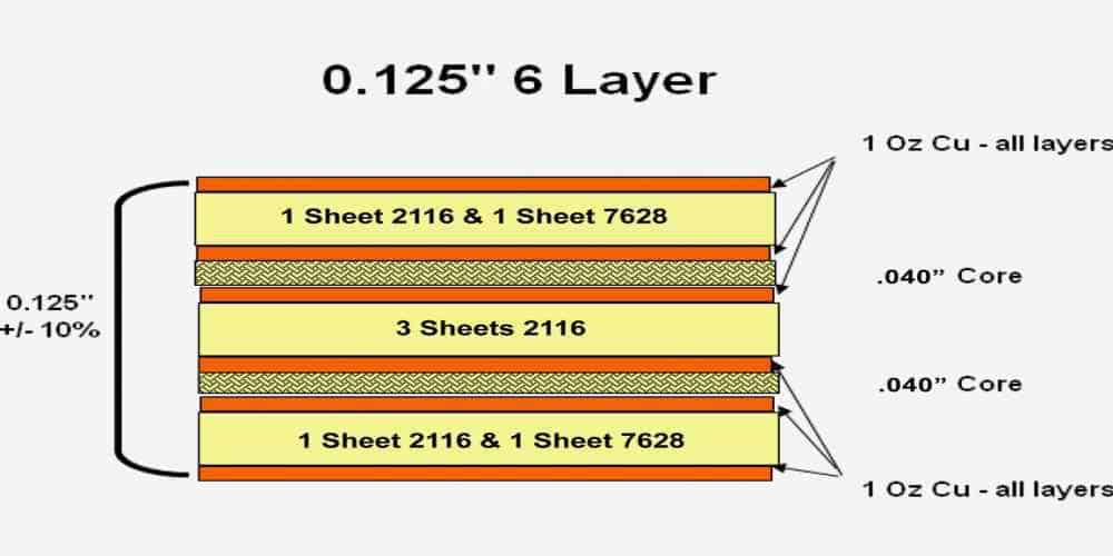
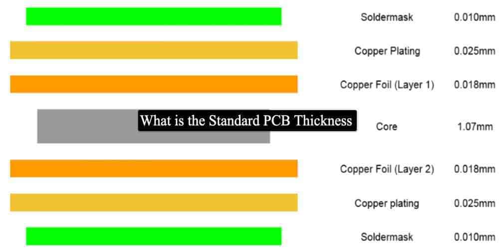
Dielectric thickness refers to the thickness of the insulating material between the layers of a PCB. In addition, it is the distance between the conductive layers of a PCB. It is the thickness of the insulating material. Dielectric thickness separates the copper layers on the PCB. The dielectric layer plays a decisive role in the performance of the PCB because these layers affect the electrical and mechanical properties of the PCB. It is necessary to choose the dielectric of the right thickness for the optimal working of the PCB.
How To Choose The Right Dielectric Thickness For Your PCB?
Designers and engineers consider many things while designing a PCB. They want to maximize the performance and as well as longevity of the board. That’s why dielectric thickness plays a crucial role. For example, if the dielectric thickness is not according to the working requirements, then you may not get the desired result from your PCB. Furthermore, it is necessary for the proper functioning of your printed circuit board that you choose the right dielectric thickness.
Choosing the right dielectric thickness for your PCB depends on several factors. These factors include the size of the printed circuit board, frequency of signals, thermal Vias, etc.
1. Operating Frequency
Operating frequency is one of the crucial factors in deciding the Right Dielectric Thickness. For high-frequency devices, a thinner dielectric layer is generally preferred. In this way, you can minimize signal loss and distortion. The more the Dielectric Thickness for your PCB, the more resistance and impedance. However, for larger or lower-frequency PCBs, a thicker dielectric layer may be necessary to provide sufficient insulation. It prevents electrical shorts and cross-talk.
2. Mechanical And Electrical Properties
Many designers neglect the Mechanical and electrical properties of the printed circuit board. It is not the right practice when it comes to choosing the right dielectric thickness PCB.
The desired electrical and mechanical properties can clearly make a difference between your expected results. For example, if the PCB requires high insulation resistance, a thicker dielectric layer can serve the purpose. On the other hand, if the PCB requires flexibility and toughness, a thinner dielectric layer may be preferred. That’s why you can say that your desired outcomes matter a lot in deciding the right dielectric Thickness of PCB. Sometimes it is also important to choose the right material for dielectric thickness according to substrate materials. Few materials are not compatible with PCB substrates due to their mechanical properties.
3. Thermal Properties
Thermal management is necessary for the efficient working of the printed circuit board. The dielectric layer is an essential component in facilitating the dissipation of heat from the Printed Circuit Board (PCB). A thicker dielectric layer, on account of its increased thermal resistance, impairs the heat dissipation process. That’s why, for high-temperature applications, it is preferable to employ a dielectric layer that is thinner in nature. So it is necessary to pay attention to the thermal properties of the materials.
4. Moisture Absorption
Moisture is the culprit of the decaying of many PCB components. Moisture is another important factor to consider when it comes to the dielectric thickness PCB. Your insulating layer must show a low moisture absorption rate. Moisture can lead to the low life of the board and corrosion of different components.
5. Heat Absorption
Heat absorption is another critical factor when it comes to deciding the dielectric thickness of PCB. Thicker layers may absorb more heat, and later it is problematic to dissipate the heat. Sometimes thinner layers are also problematic for thermal management.
What Is The Common Dielectric Materials Used In PCBs?

Material selection is a crucial part when it comes to dielectric properties. Every material is not suitable for making printed circuit boards. Because every material has different properties, and later these properties can affect the efficiency of PCB. The following are some of the most common dielectric materials used in PCBs.
FR-4 Material
FR-4 is the most common dielectric material in PCBs. This dielectric material is famous for its unique properties, such as better dielectric constant and resistance to heat and temperature.
It is made up of woven fiberglass and an epoxy resin binder. It is highly affordable with excellent mechanical and electrical properties. It is the first choice of PCB designers and manufacturers due to its high dielectric strength, low moisture absorption, and high-temperature resistance.
Rogers’s Material
Rogers is a clan of top-notch, low-leakage dielectric materials employed in high-frequency scenarios. It consists of a ceramic-laden PTFE (polytetrafluoroethylene) substance and comes in various densities and dielectric constants. Rogers possesses elevated thermal stability, minimal humidity absorption, and a low dissipation factor, which renders it an exceptional preference for high-velocity digital and RF applications.
Polyimide Material
Polyimide, a high-temperature dielectric substance, is prevalent in the manufacturing of flexible printed circuit boards (PCBs). This slim, light in weight and sturdy material is capable of withstanding extreme temperatures while remaining impervious to radiation and chemicals. Polyimide possesses a trifling dielectric constant and elevated breakdown voltage while also exhibiting exceptional dimensional stability. Therefore, it is an optimal alternative for military and aerospace uses.
Teflon Material
Teflon is available in different thicknesses and dielectric constants. It is a fluorinated thermoplastic polymer, exhibits exceptional properties that make it an exceptional candidate for high-speed digital and RF applications. Its high thermal stability ensures it can withstand high temperatures without structural deterioration, while its low moisture absorption rate means it does not readily absorb moisture from the surrounding environment.
Additionally, its low dissipation factor enables it to transmit signals with minimal energy loss, making it a prime choice for high-frequency applications. Its unique combination of properties sets it apart from other materials and positions it as a preferred choice for high-speed digital and RF applications that demand high performance. That’s why many designers, preferably Teflon, for PCB construction.
Frequently Asked Question
· Can We Adjust the Dielectric Thickness During PCB Manufacturing?
Yes, you can easily adjust the dielectric thickness of PCB manufacturing. It is not a big deal. Sometimes it is necessary to adjust the dielectric thickness during manufacturing due to various reasons. Sometimes you need to change the thickness by adding more insulating layers, while sometimes you need to reduce the layers. It varies from case to case and depends upon certain requirements.
· What Is the Ideal Dielectric Thickness for A PCB?

There is no ideal dielectric thickness for a PCB. Keep in mind that thicker dielectric layers can affect the mechanical properties of the Printed circuit boards. It can increase resistance and impudence also, but sometimes thinness is necessary to achieve the desired results. Sometimes you keep these insulating layers less thick. That’s why you cannot say there is an ideal dielectric thickness.
· Does Dielectric Thickness Affect PCB Impedance?
Yes, it does. The dielectric constant, trace width, and frequency are some basic factors to affect the impedance. Interestingly all these factors also get affected by impedance. You can optimize PCB design for better impedance performance by controlling the design process initially and later the dielectric thickness PCB. Further, you can check your PCB for validation of impedance performance.
· Can Different Parts of PCB Have Varied Dielectric Constants?
Yes, it is probably, and all new and modern devices have varied dielectric thicknesses at different parts. It improves the longevity and work efficiency of PCB. The use of different materials is helpful in achieving varied dielectric Thicknesses in different parts. That’s why you don’t need to worry if your PCB has a different dielectric thickness at every part. Remember one thing when your PCB has a different dielectric thickness; then you have to calculate the dielectric constant carefully. It can also affect other calculations, like impedance.
Conclusion
The dielectric thickness of PCB is a critical factor in the performance of a printed circuit board. It affects the electrical and mechanical properties of the PCB. It also affects the reliability and durability of the board. When choosing the dielectric thickness for your PCB, consider factors such as the frequency of signals and thermal and mechanical properties in mind.
Don’t neglect the working condition of PCB. By understanding the relationship between dielectric thickness and impedance, you can make informed decisions about the materials and design parameters. Try to choose the dielectric thickness PCB that meets your performance requirements. Remember, designing Printed circuit boards is a complicated process. Continuous improvement is key to achieving optimal dielectric thinness for better performance.
Related posts:
- The Complete Guide to Micro Electronic Assembly and How It is Disrupting the Manufacturing Industry
- Why Blue PCB is Gaining Popularity in the PCB Industry
- What Is The Average Circuit Board Cost, And What Factors Determine The Pricing?
- LTM8033IY#PBF is an EMC-Compatible µModule Buck Converter: Here’s How It Works

