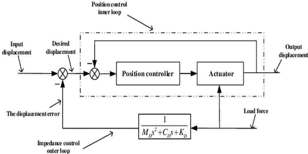
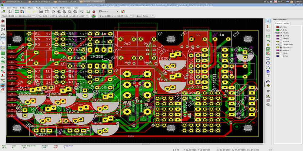
Electrical schematic design is an essential aspect of electrical engineering. It involves the creation of visual representations of electrical circuits using symbols and diagrams. These schematics are used to communicate the design of a circuit to other engineers, technicians, and manufacturers.
The purpose of an electrical schematic is to provide a clear and concise representation of the circuit design. This allows for easy understanding of the circuit’s function and operation. Schematics can be used to troubleshoot problems, identify faulty components, and improve the design of a circuit.
Creating an electrical schematic requires a thorough understanding of electrical theory and circuit design. It involves selecting the appropriate components and arranging them in a logical and efficient manner. Schematic design also requires knowledge of industry standards and regulations to ensure compliance with safety and performance requirements.

Overview
What is Electrical Schematic Design?
Electrical schematic design is the process of creating a graphical representation of an electrical system. It involves designing and documenting electrical circuits, components, and systems using symbols and lines that represent the various electrical components and their connections. Schematic diagrams are used by engineers, technicians, and electricians to understand and troubleshoot electrical systems.
Why is Electrical Schematic Design Important?
Electrical schematic design is an essential part of the design process for any electrical system. It provides a clear and concise representation of the system, which is essential for understanding how the system works and identifying potential issues. Schematic diagrams are also useful for communicating the design to other engineers, technicians, and electricians who may be involved in the construction, installation, or maintenance of the system.
In addition to providing a clear and concise representation of the system, electrical schematic design also helps to ensure that the system is safe and reliable. By carefully designing and documenting the electrical system, engineers can identify potential issues before they become problems and take steps to mitigate them. This can help to prevent electrical accidents and reduce downtime due to system failures.
Overall, electrical schematic design is a critical part of the design process for any electrical system. It provides a clear and concise representation of the system, helps to ensure that the system is safe and reliable, and is essential for understanding and troubleshooting the system.
Key Elements of Electrical Schematic Design

When designing an electrical schematic, there are several key elements that must be considered to ensure the safe and efficient operation of the system. These include symbols and notations, wiring and connections, power sources and distribution, and grounding and shielding.
Symbols and Notations
Electrical schematics use standardized symbols and notations to represent various components and functions within a system. These symbols are used to convey information about the type of component, its function, and its connection to other components in the system. It is important to use these symbols consistently and accurately to avoid confusion and ensure proper operation of the system.
Wiring and Connections
The wiring and connections within an electrical schematic are critical to the overall performance of the system. It is important to ensure that all connections are properly made and that the wiring is sized appropriately for the current and voltage requirements of the system. Additionally, wire routing and separation should be carefully considered to avoid interference and ensure proper signal transmission.
Power Sources and Distribution
The power sources and distribution within an electrical schematic are responsible for providing the necessary energy to the system. It is important to consider the type and size of power source required, as well as the distribution of power throughout the system. This includes considerations such as voltage drop, circuit protection, and load balancing.
Grounding and Shielding
Grounding and shielding are critical elements of electrical schematic design that are often overlooked. Proper grounding helps to ensure the safety of personnel and equipment, while shielding helps to reduce electromagnetic interference and ensure proper signal transmission. It is important to carefully consider the placement and routing of grounding and shielding components to ensure their effectiveness.
In summary, electrical schematic design requires careful consideration of symbols and notations, wiring and connections, power sources and distribution, and grounding and shielding. By taking these key elements into account, designers can ensure the safe and efficient operation of electrical systems.
Tools and Software for Electrical Schematic Design

When it comes to electrical schematic design, having the right tools and software can make all the difference. In this section, we’ll take a look at some of the most popular options on the market today.
CAD Software
Computer-aided design (CAD) software is a must-have for any electrical schematic designer. These programs allow you to create and edit schematics quickly and easily, while also providing a range of helpful features such as automatic error checking and parts libraries.
Some of the most popular CAD software options for electrical schematic design include:
- Altium Designer
- Eagle PCB Design
- KiCAD
- OrCAD
- Proteus
Each of these programs has its own strengths and weaknesses, so it’s important to do your research and choose the one that best fits your needs.
Simulators
Simulators are another important tool for electrical schematic designers, as they allow you to test your designs and identify potential issues before you start building. There are a variety of simulators available, ranging from simple circuit simulators to more advanced tools that can simulate entire systems.
Some popular simulators for electrical schematic design include:
- LTSpice
- PSpice
- Multisim
- CircuitMaker
Again, it’s important to choose a simulator that fits your needs and budget.
Collaboration Tools
Collaboration is key in any design project, and electrical schematic design is no exception. Fortunately, there are a variety of collaboration tools available that can help you work with your team more effectively.
Some popular collaboration tools for electrical schematic design include:
- Google Drive
- Dropbox
- Trello
- Asana
These tools can help you keep track of project timelines, share files and feedback, and stay on top of communication with your team.
Overall, having the right tools and software is essential for successful electrical schematic design. By choosing the right CAD software, simulator, and collaboration tools, you can streamline your workflow, catch potential issues early on, and work more effectively with your team.
Best Practices for Electrical Schematic Design

Standardization and Consistency
Standardization and consistency are crucial aspects of electrical schematic design. By following a set of standard practices and maintaining consistency throughout the design, you can ensure that the schematics are easy to read and understand, even for those who are not familiar with the specific project.
One way to achieve standardization is by using a template that includes all the necessary information, such as symbols, component names, and labeling conventions. This will help ensure that all schematics follow the same format and are easy to read.
Consistency is also important when it comes to labeling and naming conventions. Use clear and concise labels for all components, wires, and connections. Avoid using abbreviations or acronyms that may not be familiar to everyone.
Documentation and Labeling
Proper documentation and labeling of electrical schematics are essential for troubleshooting and maintenance. Each component should be labeled with a unique identifier and a description of its function. This will make it easier to locate and replace faulty components in the future.
In addition to component labeling, it is also important to document the wiring connections between components. This can be done using a wire list or a connection diagram. Make sure to include all necessary information, such as wire gauge, color, and termination points.
Testing and Verification
Before finalizing the electrical schematic design, it is important to test and verify the schematic to ensure it is accurate and complete. This can be done using simulation software or by physically testing the circuit.
Simulation software can be used to test the schematic in a virtual environment, which can save time and money compared to physical testing. However, physical testing should still be done to verify the accuracy of the simulation results.
Maintenance and Updates
Electrical schematics should be maintained and updated regularly to ensure they remain accurate and up-to-date. Any changes made to the circuit should be reflected in the schematic, and the schematic should be updated accordingly.
It is also important to keep a record of any changes made to the schematic, along with the reason for the change and who made the change. This will help ensure that the schematic remains accurate and can be easily updated in the future.
By following these best practices for electrical schematic design, you can ensure that your schematics are accurate, easy to read, and easy to maintain.
Challenges and Solutions in Electrical Schematic Design

Complexity and Scale
Electrical schematic design can be a challenging process, especially when dealing with complex and large-scale systems. The sheer number of components, wires, and connections can quickly become overwhelming, leading to errors and delays. To address these challenges, designers need to adopt a systematic approach that focuses on organization, simplification, and standardization.
One solution is to use modular design principles that break down the system into smaller, more manageable units. This approach allows designers to focus on one section at a time, reducing the risk of errors and improving efficiency. Additionally, using standardized symbols, labels, and templates can help ensure consistency and reduce the time required to create and update schematics.
Compatibility and Integration
Another challenge in electrical schematic design is ensuring compatibility and integration between different components and systems. With so many different manufacturers and technologies available, it can be difficult to ensure that all parts work together seamlessly.
To address this challenge, designers need to carefully research and select components that are compatible with each other and the overall system. They should also consider using software tools that can simulate and test the design before implementation, reducing the risk of compatibility issues.
Safety and Compliance
Safety and compliance are critical considerations in electrical schematic design. Failure to meet safety standards and regulations can result in serious consequences, including injury, damage, and legal liability.
To ensure safety and compliance, designers must be familiar with relevant regulations and standards, such as the National Electrical Code (NEC) and International Electrotechnical Commission (IEC) standards. They should also incorporate safety features, such as fuses, circuit breakers, and grounding, into the design.
Cost and Time Constraints
Finally, cost and time constraints are common challenges in electrical schematic design. Designers must balance the need for quality and functionality with the need for efficiency and cost-effectiveness.
To address these challenges, designers should consider using cost-effective components and materials, as well as optimizing the design for efficiency and ease of assembly. Additionally, using software tools that automate repetitive tasks and streamline the design process can help save time and reduce costs.
In summary, electrical schematic design can be a complex and challenging process, but by adopting a systematic approach and addressing key challenges, designers can create high-quality, safe, and efficient systems that meet the needs of their clients and end-users.

