PCB design is a crucial aspect of any electronic product development process. It is the foundation on which the entire product is built. PCB design plays a vital role in determining the performance, reliability, and cost of the final product. In this article, we will explore the basics of PCB design for the ESP32 microcontroller.
ESP32 is a powerful microcontroller that has gained immense popularity in recent times. It is widely used in various applications such as IoT, robotics, and automation. PCB design for ESP32 requires careful consideration of various factors such as power supply, signal integrity, and thermal management. The design should be optimized for the specific application requirements to ensure optimal performance and reliability.
In this article, we will cover the essential aspects of ESP32 PCB design, including schematic design, component selection, layout design, and manufacturing considerations. We will provide practical tips and guidelines to help you design a robust and reliable PCB for your ESP32-based project. Whether you are a beginner or an experienced designer, this article will provide valuable insights and best practices for designing high-quality PCBs for ESP32.
ESP32 Overview
The ESP32 is a powerful and versatile microcontroller that is often used in printed circuit board (PCB) designs. It is designed and manufactured by Espressif Systems, a company that specializes in creating high-performance and low-power microcontrollers for a variety of applications.
Features
The ESP32 has a wide range of features that make it a popular choice for PCB designers. Some of its key features include:
- Dual-core processor: The ESP32 has a dual-core processor that allows it to handle complex tasks and run multiple programs simultaneously.
- Wi-Fi and Bluetooth connectivity: The ESP32 has built-in Wi-Fi and Bluetooth capabilities, which makes it easy to connect to the internet and other devices.
- Low power consumption: The ESP32 is designed to consume very little power, which makes it ideal for battery-powered devices.
- Rich peripheral set: The ESP32 has a rich set of peripherals, including ADCs, DACs, SPI, I2C, UART, and more. This makes it easy to interface with other devices and sensors.
- Secure boot and flash encryption: The ESP32 has built-in security features that help protect against unauthorized access and data theft.
Benefits
The ESP32 offers a number of benefits for PCB designers, including:
- High performance: The ESP32 is a powerful microcontroller that can handle complex tasks and run multiple programs simultaneously.
- Low power consumption: The ESP32 is designed to consume very little power, which makes it ideal for battery-powered devices.
- Easy to use: The ESP32 is easy to use and comes with a variety of development tools and resources that make it easy to get started.
- Cost-effective: The ESP32 is a cost-effective solution for many applications, which makes it a popular choice for PCB designers.
- Reliable: The ESP32 is a reliable microcontroller that is designed to operate in a variety of environments and conditions.
In summary, the ESP32 is a powerful and versatile microcontroller that offers a wide range of features and benefits for PCB designers. Its dual-core processor, Wi-Fi and Bluetooth connectivity, low power consumption, rich peripheral set, and built-in security features make it an ideal choice for a variety of applications.
PCB Design Guidelines

When designing a PCB for an ESP32 project, it is important to follow certain guidelines to ensure optimal performance and reliability. The following sections provide considerations for schematic and layout design.
Design Considerations
Before starting the PCB design, it is important to consider the following factors:
- Power requirements: Ensure that the power supply is sufficient for the ESP32 and any other components on the board.
- Signal integrity: Consider the signal paths and ensure that there is minimal noise and interference.
- Thermal management: Plan for proper heat dissipation to prevent overheating.
- Mechanical constraints: Consider the size and shape of the board to fit within the enclosure and any mounting requirements.
Schematic Design
When creating the schematic, keep the following in mind:
- Use the recommended ESP32 schematic symbols and footprints.
- Place decoupling capacitors close to the power pins of the ESP32.
- Add pull-up or pull-down resistors to unused pins to prevent floating inputs.
- Use a separate ground plane for analog and digital signals to minimize noise.
Layout Design
When laying out the PCB, consider the following:
- Place components in a logical and organized manner.
- Keep signal traces as short as possible to minimize noise and interference.
- Use a ground plane to provide a low-impedance return path for signals.
- Route high-speed signals first and keep them away from sensitive analog signals.
- Use vias to connect layers and provide a low-impedance path for signals.
By following these guidelines, you can create a well-designed PCB for your ESP32 project that provides optimal performance and reliability.
ESP32 PCB Design Example
When designing a PCB for the ESP32 microcontroller, there are a few key considerations to keep in mind. Here, we’ll walk through an example of a simple ESP32 PCB design.
Schematic Design
The first step in designing a PCB for the ESP32 is to create a schematic. This schematic will serve as the blueprint for the rest of the design process. When creating the schematic, it’s important to keep the following in mind:
- Use the correct pinout for the ESP32 module you’re using.
- Ensure that the power supply and decoupling capacitors are properly connected.
- Include any additional components required by your specific project, such as sensors or LEDs.
PCB Layout
Once the schematic is complete, it’s time to lay out the PCB. When laying out the PCB, it’s important to consider the following:
- Place components in a logical and organized manner to minimize signal interference.
- Keep traces as short as possible to minimize signal loss.
- Ensure that the power and ground planes are properly connected.
Example Design
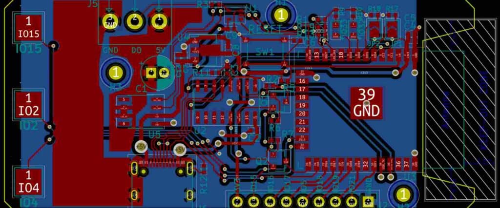
Here is an example of a simple ESP32 PCB design:

In this design, the ESP32 module is located in the center of the board, with the power supply and decoupling capacitors located nearby. The board also includes a few additional components, such as an LED and a push button.
Overall, this design is simple and straightforward, but it includes all of the necessary components for a basic ESP32 project. With a little bit of tweaking, this design could be adapted for a wide range of projects.
Testing and Debugging

Testing Methods
When it comes to testing PCB designs with ESP32, there are several methods that can be used to ensure that the board is functioning as expected. One of the most common methods is to use a multimeter to test the voltage and continuity of the board’s connections. This can help identify any potential shorts or open circuits that may be present.
Another testing method is to use a logic analyzer to monitor the signals on the board. This can be especially helpful when working with complex designs that involve multiple signals or protocols. By monitoring the signals in real-time, it’s possible to identify any issues that may be present and take corrective action.
Debugging Techniques
Debugging PCB designs with ESP32 can be a challenging process, but there are several techniques that can be used to make it easier. One of the most important techniques is to use a debugger to step through the code and identify any errors that may be present.
Another technique that can be helpful is to use a serial console to monitor the output of the board. This can be especially useful for identifying issues with the firmware or software running on the board.
When debugging PCB designs with ESP32, it’s also important to have a good understanding of the board’s hardware and software. This can help identify any potential issues and make it easier to find a solution.
Overall, testing and debugging PCB designs with ESP32 can be a challenging process, but by using the right techniques and tools, it’s possible to identify and resolve any issues that may be present.
Conclusion
In conclusion, PCB design for ESP32 is a complex process that requires careful planning and attention to detail. While there are many factors to consider when designing a PCB for an ESP32, including signal integrity, power requirements, and thermal management, the end result can be a highly functional and reliable device.
Effective PCB design requires a thorough understanding of the ESP32’s capabilities, as well as the specific requirements of the application in question. Designers must also be familiar with the latest tools and techniques for PCB design, including schematic capture, layout, and simulation software.
Overall, successful PCB design for ESP32 is a collaborative process that involves close collaboration between hardware and software engineers, as well as other stakeholders. By following best practices for PCB design and leveraging the latest tools and techniques, designers can create highly functional and reliable devices that meet the needs of a wide range of applications.
