Mac PCB layout is an essential aspect of designing and manufacturing electronic devices. PCB (Printed Circuit Board) is a board that connects different electronic components to form a functional circuit. Mac PCB layout involves designing the placement of electronic components, routing connections between them, and optimizing the layout for performance and manufacturability.
The design of a PCB can significantly impact the performance, reliability, and cost of an electronic device. Mac PCB layout involves careful consideration of factors such as signal integrity, power distribution, thermal management, and manufacturability. A well-designed PCB can reduce noise, improve signal quality, and minimize electromagnetic interference (EMI). It can also optimize power distribution, reduce heat dissipation, and simplify assembly and testing.
In summary, Mac PCB layout is a critical aspect of electronic device design and manufacturing. It involves designing the placement and routing of electronic components on a PCB board while considering factors such as signal integrity, power distribution, thermal management, and manufacturability. A well-designed PCB can significantly improve the performance, reliability, and cost-effectiveness of an electronic device.

Basics of PCB Layout
What is a PCB Layout?
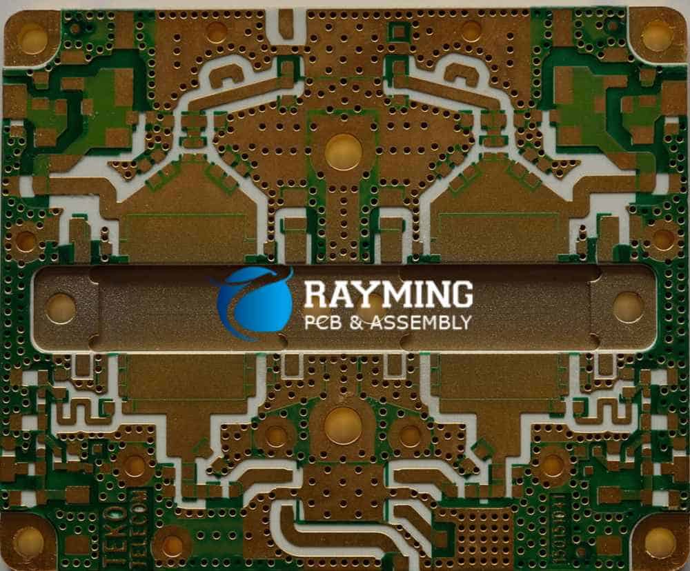
A Printed Circuit Board (PCB) layout is a physical representation of the electronic circuit. It is the design that is used to manufacture the PCB. The layout consists of a two-dimensional drawing of the copper traces, vias, and pads that connect the electronic components. PCB layouts are created using specialized software, which allows designers to place and route the components and their connections.
Why is PCB Layout Important?
The PCB layout is a critical part of the electronic design process. A good layout can ensure that the circuit functions correctly, is reliable, and is easy to manufacture. A poor layout can result in electrical noise, signal integrity problems, and even complete circuit failure. A well-designed PCB layout can also reduce the size of the circuit, making it more compact and easier to fit into a product.
Components of a PCB Layout
The PCB layout consists of several components, including:
-
Components: These are the electronic parts that are placed on the PCB. They include resistors, capacitors, diodes, transistors, and integrated circuits.
-
Traces: These are the copper connections that connect the components on the PCB. Traces can be of different widths, depending on the current they need to carry.
-
Vias: These are holes in the PCB that allow connections to be made between different layers of the board.
-
Pads: These are the copper areas where the components are soldered to the PCB.
-
Silkscreen: This is the layer of the PCB that contains markings such as component values, part numbers, and other information.
In conclusion, understanding the basics of PCB layout is essential for designing electronic circuits that are reliable, efficient, and easy to manufacture. By paying attention to the components of the layout, designers can create circuits that are optimized for performance and functionality.
Mac PCB Layout Software

Overview of Mac PCB Layout Software
Mac PCB layout software is a tool that allows users to design and layout printed circuit boards (PCBs) on a Mac computer. This software is specifically designed for Mac users and provides an intuitive interface that makes it easy to create complex PCB designs.
Features of Mac PCB Layout Software
Mac PCB layout software comes with a range of features that make it a powerful tool for PCB design. Some of the key features include:
-
Intuitive user interface: The software comes with an easy-to-use interface that makes it easy to create complex PCB designs.
-
Design rule checking: The software checks the design rules to ensure that the PCB design meets the required specifications.
-
3D visualization: The software provides a 3D visualization of the PCB design, allowing users to see how the design will look in real life.
-
Auto-routing: The software comes with an auto-routing feature that automatically routes the traces on the PCB.
-
Component libraries: The software comes with a range of component libraries that users can use to quickly create PCB designs.
Benefits of Using Mac PCB Layout Software
Using Mac PCB layout software offers a range of benefits, including:
-
Increased productivity: The software’s intuitive interface and powerful features help users to design PCBs quickly and efficiently, increasing productivity.
-
Improved accuracy: The software checks the design rules to ensure that the PCB design meets the required specifications, improving accuracy.
-
Reduced errors: The software’s auto-routing feature reduces the chances of errors in the PCB design.
-
Easy collaboration: The software allows users to collaborate on PCB designs, making it easy to work with a team.
Overall, Mac PCB layout software is a powerful tool that offers a range of features and benefits for PCB design.
Designing a Mac PCB Layout
Steps for Designing a Mac PCB Layout
Designing a PCB layout for a Mac involves several steps. Here are some of the essential steps that you need to follow:
-
Start with a schematic diagram: Before designing a PCB layout, you need to have a schematic diagram of the circuit. A schematic diagram will help you to understand the functionality of the circuit and how the components are connected.
-
Place components: Once you have a schematic diagram, the next step is to place the components on the PCB layout. You need to place the components in a way that they are easily accessible and do not interfere with each other.
-
Route the traces: After placing the components, the next step is to route the traces. While routing the traces, you need to ensure that there are no crossovers, and the traces are of the correct length.
-
Place vias: Vias are used to connect the traces on different layers of the PCB. You need to place vias in a way that they do not interfere with the components.
-
Add ground and power planes: Ground and power planes are essential for a stable circuit. You need to add ground and power planes to the PCB layout.
Considerations for Designing a Mac PCB Layout

While designing a Mac PCB layout, you need to consider the following factors:
-
Size: The size of the PCB should be small enough to fit into the Mac.
-
Power consumption: The power consumption of the circuit should be low to avoid overheating.
-
Noise: The circuit should be designed in a way that it does not produce unwanted noise.
-
Heat dissipation: The circuit should be designed in a way that it can dissipate heat efficiently.
Tools Needed for Designing a Mac PCB Layout
To design a Mac PCB layout, you need the following tools:
-
PCB design software: You need a PCB design software to create the PCB layout.
-
Schematic capture software: You need a schematic capture software to create the schematic diagram.
-
PCB manufacturer: You need a PCB manufacturer to fabricate the PCB.
-
Components: You need components to place on the PCB.
In conclusion, designing a Mac PCB layout involves several steps, considerations, and tools. By following the steps and considering the factors, you can design a high-quality Mac PCB layout.
Testing and Troubleshooting Mac PCB Layouts

Importance of Testing and Troubleshooting
Testing and troubleshooting are essential steps in the development process of any electronic device, including Mac PCB layouts. Testing ensures that the circuit functions as intended, while troubleshooting helps to identify and fix any issues that may arise during the testing process.
Mac PCB layouts are complex and require careful attention to detail during the design and testing phases. Testing and troubleshooting can help to ensure that the final product is reliable, efficient, and meets the requirements of the end-user.
Common Issues with Mac PCB Layouts
There are several common issues that can arise when testing and troubleshooting Mac PCB layouts. These issues include:
-
Short circuits: When two or more electrical paths come into contact with each other, causing a short circuit. This can lead to damage to the circuit and other components.
-
Open circuits: When a circuit fails to complete due to a break in the electrical path. This can prevent the circuit from functioning correctly.
-
Noise: Electrical noise can interfere with the signal in the circuit, causing errors and incorrect readings.
-
Grounding issues: Poor grounding can lead to noise and other issues with the circuit.
Tools for Testing and Troubleshooting Mac PCB Layouts
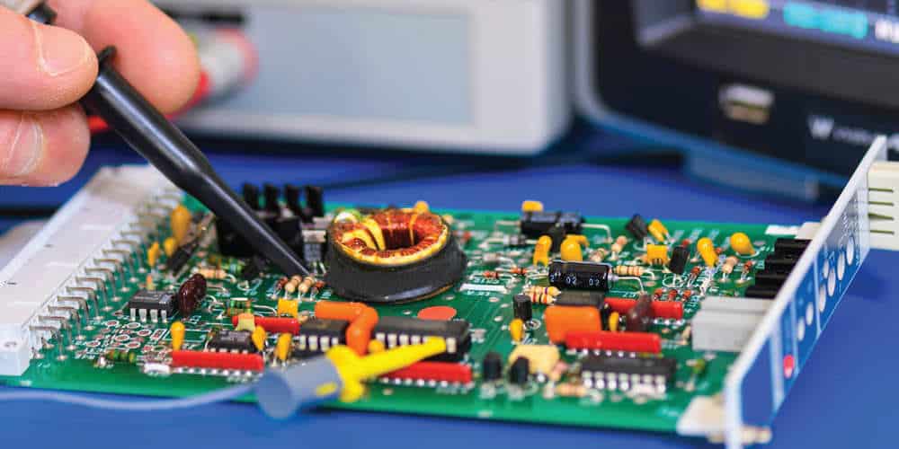
There are several tools that can be used to test and troubleshoot Mac PCB layouts. These include:
-
Multimeters: Used to measure voltage, current, and resistance in the circuit.
-
Oscilloscopes: Used to measure the waveform of the signal in the circuit.
-
Logic analyzers: Used to analyze the digital signals in the circuit.
-
Spectrum analyzers: Used to analyze the frequency spectrum of the signal in the circuit.
-
Thermal imaging cameras: Used to detect any hot spots or overheating in the circuit.
In conclusion, testing and troubleshooting are essential steps in the development process of Mac PCB layouts. By identifying and fixing any issues that may arise, designers can ensure that the final product is reliable, efficient, and meets the requirements of the end-user.

