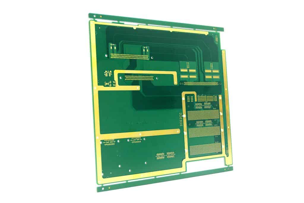
The Metal Core PCB (MCPCB) is a type of surface-mounting package used in the electronics industry. MCPCB has no lead, has less weight and occupies less space than conventional PCBs. In addition, MCPCBs have better mechanical properties and circuit performance than conventional PCBs.
A Metal Core PCB is a PCB that has a metal core and is applicable for heating, cooling, and other applications. This type of PCB requires an entire documentation package and special tools for design. Choosing the right tools for metal core PCB layout design is essential to ensure a successful product. Layout tools help place components, define vias, and route traces. They also let you crosscheck electrical and thermal loads.
The purpose of the Metal Core PCB is to reduce the total amount of conductive material in contact with the component. You can accomplish this by ensuring that the MCPCB contains a metal core 40 mils to 50 mils larger than the plated through-hole component. In addition, this metal core contains non-conductive epoxy filler.

Metal Core PCBs
Metal Core PCBs are printed circuit boards that use copper or aluminum as a core material. The design process for a metal core PCB is the same as that for other printed circuit boards, except the substrate material is metal. However, the material used for the core is different and requires special considerations for the manufacturing process. This includes the use of thermal insulating layers and metal plates.
You must consider several factors during the design process, including solder mask, metal fabrication, and mechanical operations. These factors will affect the final product.
The advantages of using this type of PCB are numerous.
- It saves space on the board, since it replaces heat sinks.
- The metal substrate allows mounting power transistors directly on it.
- Metal core PCBs reduce the number of interconnects, which improves heat transfer.
- Additionally, metal core PCBs allow designers to eliminate entire sections of printed wiring boards and interconnects. This also allows designers to use surface mount devices instead of discrete ones, reducing space on the board.
Metal Core PCBs also have the advantage of being more durable than traditional FR-4 PCBs. The special substrate material is designed to withstand high temperatures and dissipate surplus heat from devices. The resulting thermal dissipation is nine times faster than regular FR-4 PCBs. Furthermore, the material is mechanically solid. Metal Core PCBs are available in different configurations.
Other Advantages
We also refer to Metal Core PCB as a thermal PCB. The base metal is an excellent heat conductor, distributing the heat generated by the semiconductors during operation. As a result, they can be a good replacement for conventional FR4 and CEM3 materials. Metal Core PCBs also help to prevent hot spots near sensitive components.
Metal Core PCBs are usually a bit thicker than other types of PCBs. Choosing a thickness that’s optimal for your needs will ensure the best functionality of your PCB. Different manufacturers also offer different thicknesses for their boards. Therefore, you should consider the thickness before ordering your metal core PCBs.
Thermal Conductivity
Thermal conductivity is an important factor to consider when designing a PCB board. The more thermally-conductive the board, the more efficient it is. For MCPCBs, the bottom side is entirely composed of metal, which is much more thermally conductive than the top side. Moreover, MCPCBs require minimal drilling, with only a few large holes required for mounting.
LED modules, for example, are characterized by high heat flux, which requires efficient thermal simulation.
The main purpose of a PCB is to prevent the components from overheating. This ensures optimal performance and increases the component’s lifespan. Compared to traditional FR4 PCBs, MCPCBs are up to eight times more efficient at dissipating heat. This is because they are made of a metal substrate, which transfers the heat away from critical parts of the board and towards less critical areas.
High-power Semiconductor light sources, such as LEDs, generate heat, and Metal Core Printed Circuit Boards are ideal for dissipating it. As a result, MCPCBs have nearly unlimited potential. And because of their superior thermal characteristics, they apply in various applications.
An MCPCB has a copper core surrounded by a base metal. These PCBs have higher thermal conductivity than FR-4, making them more suitable for high-temperature environments. A Metal Core PCB also has a dielectric layer between the copper foil and the metal core, which has a high thermal conductivity.
Heat sinks and copper foil

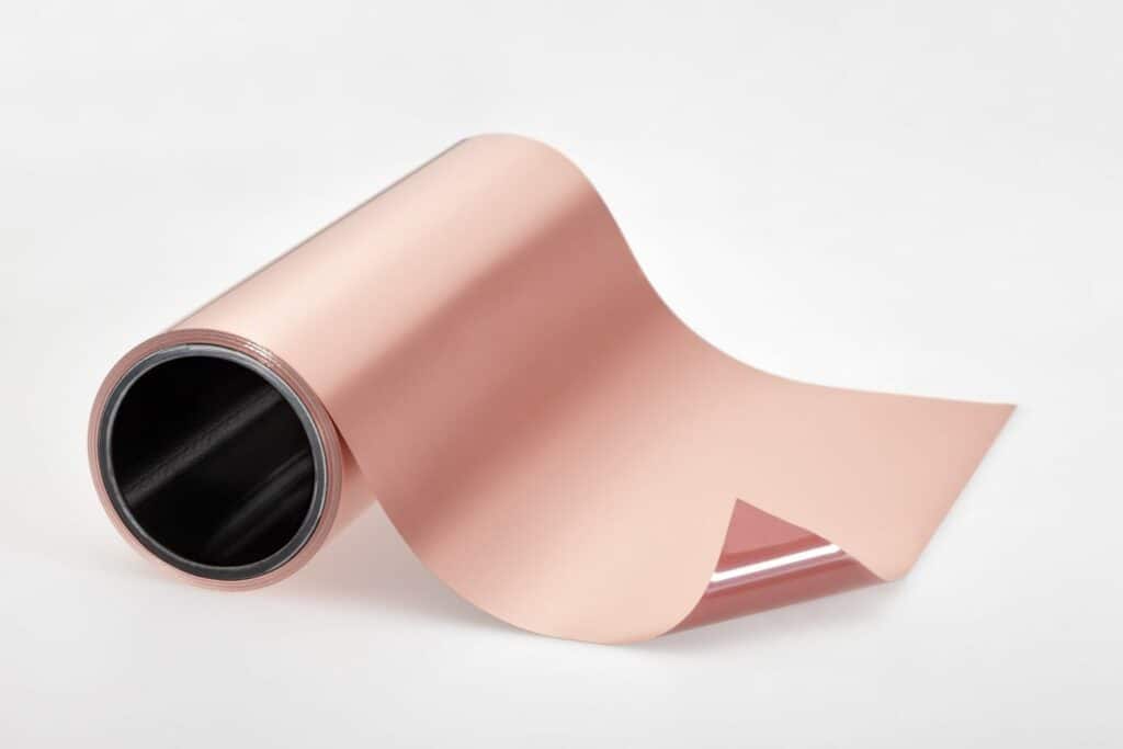
Copper foil is a primary component of a multi-layer copper-foil circuit board (MCPCB). Its thickness varies from about 50 to 200 microns. Copper foil is the preferred material for MCPCBs due to its high thermal conductivity and electrical insulation. In addition, it is highly resistant to moisture and is ideal for power devices and cooling systems.
MCPCBs have copper foil and aluminum cores. Copper foil is the top copper layer that is electrically isolated from the base layer of aluminum. The copper foil also plays a key role in ensuring that heat transfer is quick and efficient. Copper foil is also an excellent thermal conductor, as it allows efficient dispersal of heat.
You make an MCPCB from copper foil and a thin layer of insulating material. Place the copper foil on each side of a metal core. You then etch the copper foil into the desired circuit pattern. The copper foil is about one to ten oz thick and bonded to a metal plate of around 0.8 mm to 1.6 mm in thickness.
Copper PCBs made from thicker copper foil are more effective at carrying current for the same route width. It also offers more protection from bending or bowing due to increased conductivity. As copper thickness increases, the weight of the board increases. However, copper PCBs with thick copper foil can be difficult to etch and result in heavy undercutting.
Metal-clad PCBs are a more expensive alternative to traditional FR4 boards, but the advantages of a copper-based PCB are worth considering. This material provides enhanced durability and greater shelf life compared to aluminum-based PCBs. Copper-based PCBs also tend to be more stable than aluminum core PCB.
Metal Core Boards and Heat Generating Components
Metal Core Boards (MCBs) are an excellent choice for applications that generate high amounts of heat. Without proper heat dissipation, the electronic components in a circuit could suffer damage. Due to their dielectric properties, MCBs can quickly dissipate heat. The dielectric material acts as a thermal link between the IC components and the metal plate, reducing heat buildup and improving efficiency and performance.
The metals we use for MCBs include copper and aluminum. Most prefer copper over aluminum because of its superior heat transfer. However, copper is a more expensive and heavier material. In addition, it requires more intricate machining and is prone to corrosion. Moreover, we can etch metal-core PCBs to control heat flow. They are also highly reliable. Manufacturers can manufacture MCBs in a variety of thicknesses and copper foil weights.
We use the MCPCB in many power electronics applications. For example, they are common in switching supply and LED light circuits. You can use copper or aluminum to make the MCPCB and can be single or double-sided. However, they are also available in multilayered hybrid versions incorporating FR4 material.
The PCBs used in consumer electronic devices generate a lot of heat. This heat is generated because the components are constantly charging and discharging. We use the MCPCB in these applications because they can dissipate heat efficiently. LED light bulbs are a few common examples of MCPCBs that generate excessive heat.
Metal Core PCBs are ideal for applications that produce enormous amounts of heat and can’t cool down with conventional fans and other cooling methods. They also have the advantage of allowing high illumination levels with less energy than LEDs. They are also useful for military and aerospace applications requiring high temperatures and frequent mechanical shocks.
Metal Core PCB Applications
We must follow several design guidelines when designing PCBs for metal core applications. The first step is to determine the metal core layer locations. Normally, we use aluminum, but copper and stainless steel are also common. The next step involves defining the dielectric layers. This sets the foundation for routing traces and placing components.
For example, if you are designing a circuit board that generates a lot of heat, you’ll want to choose a metal core PCB. This is one of the fastest methods to cool your PCB, and it is available in one and two-layer designs. Metal core PCBs also feature NPTH Drills, larger than PTH drills. In addition, they are often topped with a metal plate for added heat transfer.
Generally, we use metal PCBs in high-power applications such as LED lighting, solid-state relays, and motor control in electric vehicles. They are also ideal for applications where high-temperature environments are present. Their high thermal conductivity makes them a superior option for these high-temperature applications than traditional FR-4 substrates. Aluminum is the most common metal used in the metal layer, as it has excellent thermal conductivity, high breakdown voltage, and high tensile strength.
As far as durability is concerned, a metal core PCB is more expensive than an aluminum PCB, but has better performance. Copper corrodes easily, while aluminum does not. Besides, metal core PCBs integrate a dielectric polymer layer with high thermal conductivity. This allows for faster heat transfer. Another advantage to metal core PCBs is that they are non-toxic and recyclable.
Metal Core PCBs are an excellent alternative to FR-4 and CEM3. They are more durable and thermally conductive than their FR-4 counterparts, making them an excellent choice for high-temperature applications.

