Wiring your prototype board involves soldering through-hole components and connecting them to other pins. You should follow a soldering iron guide to help you do this. Once you have soldered the pins to each other, you can use your soldering iron to connect the leads. Alternatively, you can use jumper wires to connect components. You can also use copper traces.
Jumper wires
Jumper wires are a convenient way to connect components on a breadboard. They are made of pure copper or PVC wire and have good conductivity. They are available in 4 different sizes and a variety of colors. You can use the wires for circuit experimentation to connect your components. Each package contains 60 different color wires.
During prototyping, jumper wires are an essential part of the design process. They allow you to quickly connect different components to their respective PINs on a microcontroller. So often, circuits can get messy and require a lot of circuit sanity checks. Using the right wires, you can keep your circuits organized and minimize rework time.
When choosing a wire, it is essential to choose one with good quality and reliability. We manufacture SHOWA SEISEN jumper wires under strict quality control standards. The wire is vacuum-packed to prevent rusting during transportation. They are shipped to many countries worldwide.
Jumper wires can connect two ports on a breadboard. These wires come in different sizes. Some of the most common sizes are male-to-male and male-to-female. In addition to this, there are also female-to-female jumper wires.
Solder
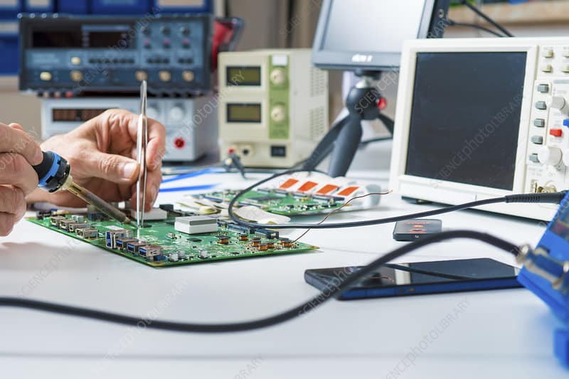
Soldering a prototype board is essential in building and testing your prototype circuit. But, first, you need a high-quality prototyping board. Prototype boards are typically made of paper or resin and can withstand the heat generated during soldering. However, it is essential to use proper precautions when soldering the board.
Soldering a prototype board involves the application of solder to various components. You can solder the components onto the board directly, or you can use wire to connect components. In either case, checking the circuit diagram before you begin soldering is essential. In addition, you can also use a breadboard to attach components.
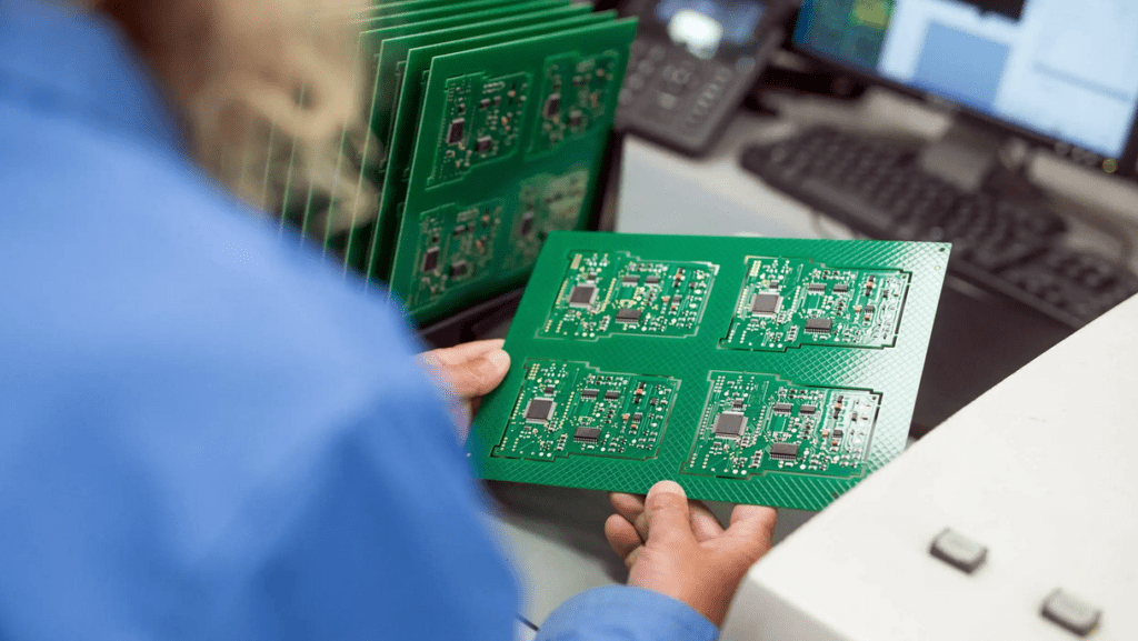
Prototype boards usually have holes that are pre-drilled at standard intervals. Copper pads usually surround these holes. It is also possible to purchase bare perfboard sheets. However, if you need to make more complex prototypes, you can opt for a better-quality perfboard with pads on both sides. The connections between the pads on a perfboard consist of wire wrap or miniature point-to-point wiring.
You can also use a jumper wire, which is extremely handy for prototyping using a solderless breadboard. It is a handy tool purchased cheaply or made at home. Jumper wires come with connector pins on both ends, ideal for connecting two points without soldering. Jumper wires are also available in different lengths and colors, which makes it easier to identify the connections.
Mousebites
We can construct prototype boards in two basic ways. You can use the “pad per hole” design, where we make the board with individual pads made of copper, or the “stripboard” design, which uses strips of copper running parallel along the board. Both designs allow you to insert wires into the holes and test the connections.
Prototype boards are ideal for planning projects. They have rows and columns of holes and can be connected with solder or without it. It is necessary to test your circuit diagram first before soldering it to the prototype board. You can also use a breadboard if you do not intend to solder your components.
Copper traces
Copper traces are an essential feature of printed circuit boards. These etched copper tracks carry current. To increase their current carrying capacity, we can widen copper traces. Another option is to use heavy copper to improve efficiency and heat management. The PCB industry considers copper that weighs three ounces or more as heavy copper.
Using the proper solder paste when soldering on copper traces is essential. However, not all solder paste is lead-free. Lead-lead solder can cause problems with copper traces. Therefore, lead-free solder paste is the best choice. In addition, copper traces on a prototype board are not as easily accessible as soldered copper traces.
The copper trace’s current carrying capacity depends on its cross-sectional area and temperature rise. For example, a 10-mil copper trace with one ounce of copper weight can carry about one amp at most. On the other hand, a 50-mil copper trace can carry about twice as much current.
A basic PCB is a flat sheet of insulating material with a layer of copper. A photochemical process then etches the copper layer into separate conducting lines, pad areas, and solid conductive areas. These tracks and pads are used as wires in the circuit and serve as connection points for components. Solid conductive areas on the board also help to interconnect multiple layers of the board and to shield components from electromagnetic radiation. We then cover the copper layer with a solder mask, which gives the PCB its green color.
Schematics
The process of wiring a prototype board begins with the creation of schematics. A schematic is a drawing that defines the connections between the various components. After defining all the components, the next step is to design the circuit board’s layout. Using a schematic editor, determine where to place each component and draw the tracks to connect them. After the layout is complete, click the Update PCB button to load the footprints of the board.
It is essential to know how to read a schematic. First, it should depict the connection between the components and the circuit. The letters indicate which type of component they are. To identify a specific component in a schematic, it is essential to know the component’s name. For example, if multiple resistors exist in the circuit, each one should be named R1 or R2, etc.
In addition to the schematic, the netlist file is a critical component in the design process. The netlist file is where schematics and PCB databases come together. This file consists of several specialized sections.
Perfboard
There are two basic types of circuit boards: perf boards and stripboards. Perf boards feature individual copper pads, or “perfs,” to which you can connect wires. Stripboards, on the other hand, are made of copper strips that run parallel to the length of the board. These strips serve as circuits’ wires, and we can easily trim and reshape them to fit your needs.
You can plan out the wiring of your prototype board using board-planning software. Some software works with both perfboard and stripboard. You can also draw the layout on graph paper. Note the breakpoints to connect components. Then, solder the conductive strips in place.
Prototype boards are commonly helpful in electronic prototyping projects. This type of board has many holes to connect various electronic elements. They can be as large or as small as you like, but most have about 30 or 60 rows of holes. They also include a ground and power distribution rail.
When wiring a prototype board, ensure the circuits you want to use are the same as the final product. Prototype boards are a great way to test new ideas and see how they work before you invest your time and money into the final product. A breadboard is also a great way to ensure your design works as intended.
