Printed circuit boards comprise a wide range of electronic components. These components play crucial roles in the functioning of electronic circuits. Resistors are basic electronic components on a printed circuit board. A circuit board will never function without resistors. Resistors regulate the flow of current and make LEDs light up. No components can ever match the performance and function of a resistor.
Also, resistors are primarily made to regulate current flow and ensure the smooth operations of LED lights. There are more functions of resistors. In case you don’t know the functions of resistors, this article has got you covered.
What are Resistors?
Resistors are passive electronic components available in all circuit boards. Electronic manufacturers integrate resistors for several reasons. The function of resistors is to resist current flow by discharging electric power as heat. Also, resistors prevent electric devices from burning out. This is one of the reasons they are usually placed behind LED lights.
Resistors prevent burn out in devices when there is irregular electric current. Also, resistors serve several purposes which include voltage division, delimited electric current, control gain, and heat generation. Resistance represents the value of this electronic component. Also, resistance is usually measured in ohms. There are different types of resistors.
Furthermore, resistors can only consume power but can’t produce it. Therefore, they are often regarded as passive components. To understand the functions of resistors well, you will need to understand Ohm’s law. There are three major attributes of electrical circuit which are resistance, current, and voltage.
Resistors are usually made of materials that can restrict electricity flow. According to Ohm’s law, the voltage across a resistor is proportional to the flow of current through the resistance.
Types of Resistors
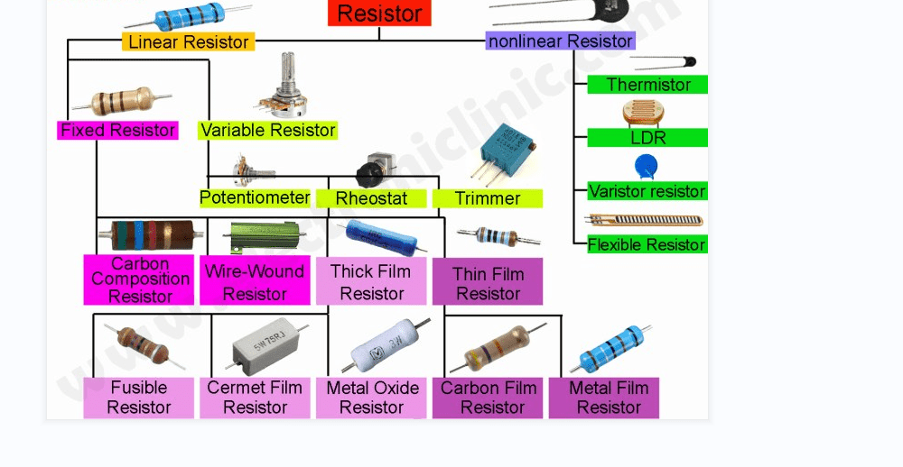
There are several types of resistors.
Fixed value resistors
Fixed resistors feature a fixed tolerance and resistance irrespective of any changes in factors like light and temperature. Also, they are a common type of resistor. Fixed resistors are known as the most frequently used resistors on printed circuit boards.
Variable resistors
Variable resistors experience change in their resistance. Their resistance is modifiable. A good example of a variable resistor is the potentiometer which features a dial you can ramp up or down.
Physical quality resistors
The resistance of these resistors can change according to various physical properties like light levels, temperature, and magnetic field. Examples of physical quality resistors include varistor, thermistor, and photoresistor.
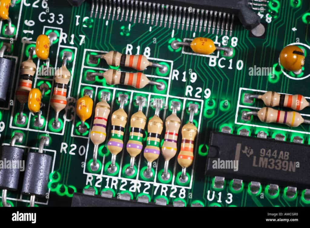
Through hole resistors
Through hole resistors have leads on any of their ends. They are usually bent over for insertion and soldering in the holes of the PCB. Also, through hole resistors are available in different heights, lengths, and widths. These resistors comprise bands of several colors to identify their tolerances and values.
Through hole resistors are ideal for use in prototyping and breadboarding. However, these resistors can take more space. Through hole resistors are usually packaged in axial package.
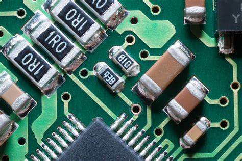
Surface mount resistors
Surface mount resistors are widely used in surface mount packages soldered directly on the metal pads on the PCB board. Also, these resistors are smaller than through hole resistors. Also, SMT resistors take less space than through hole resistors. The tolerances and values of surface mount technology resistors are usually stamped on them.
Functions of Resistors
The letter “R” represents resistors. Resistors serve several functions in printed circuit boards and electronic devices. Some of these functions include:
Voltage division
A resistor divides voltage when combined with another component like a bulb. For instance, if the sum of voltages of the bulb and resistor is equivalent to the total voltage across the bulb and the resistor, it will divide voltage.
Impedance matching
Impedance matching involves adapting the load impedance to the excitation source’s internal impedance to obtain a maximum power output when signal is transmitting. You can change the impedance in this case.
Voltage drop
Resistors create proper voltage by enabling a voltage drop. Elements in an electrical circuit need a specific amount of voltage.
Delimit electric current
Electric current usually rise from “charge flow.” Resistors can limit electrons flow by simply reducing current. Also, these electrical components determine the amount of current flow for a particular voltage.
Data and address bus pull-ups
This minimizes noise on high-speed computer buses. Also, if a data bus tria-states, it is important to pull it in an already known state to ensure the output is high beyond switching.
Powering LEDs
Light emitting diodes will burn out when there is too much current passing through them. However, a resistor can prevent this from happening when you connect them right behind a light emitting diode. Resistors will help you regulate the amount of current received by the LED.
How to Measure a Resistor
The value of a resistor is resistance (R). There are different ways to display this value. Also, the SMD codes or color-coded makers are two standards that display resistance.
Color coding
Color coding displays tolerance and resistance values by using colored bands. These color bands are usually painted on the resistor’s body. Most resistors usually have four colored bands. The first two bands indicate the primary digits of the resistance while the third band indicates the multiplying factor, which is a decimal multiplier. Also, the third band reveals the powers of 10 the first two numbers will be multiplied by.
The fourth band which is the final band offers a tolerance value. It reveals the accuracy of the resistance value. However, a resistor could have five bands. In this case, the first three bands represent the resistance value while the fourth band will be the multiplying factor. The fifth band indicates the tolerance value. Five band resistors are more accurate. Also, their tolerance value is lower. All colors on a resistor match with different numbers. A color code calculator can help you determine these values.
SMD codes
Sometimes, you might not be able to identify a resistor by color-coding. This is because not all resistors are large. For instance, resistors used in surface mount devices (SMDs) are very small. Therefore, SMD resistors have a numerical-based code. For instance, a modern PCB features SMD resistors. These resistors have similar sizes. Therefore, this standardizes the manufacturing process with the help of pick and place machines.
How to Choose the Right Resistor
Resistors are available in different types. Therefore, it is crucial to consider some factors when choosing a resistor.
Resistance
When calculating the resistance of a resistor, you will need the Ohm’s law. You can integrate any of these formulas; V=IR, R=V/I or I=V/R. Where R is known as the resistance, I is the current and V is the voltage.
Power rating
You need to determine how much power you need your resistor to dissipate. Also, the formula below can help you calculate power rating accurately. P=V2/R. Here R refers to the resistance, V is the voltage drop, and P is the power.
Choose a resistor
After you have determined your power rating values and resistance, you will need to choose the resistor from a component distributor. It is advisable you use the standard type of resistor if you want a durable PCB.
Resistor Material Types
Resistors can be classified according to the material used in making them. These materials include carbon, metal oxide film, and wire wound among others. However, the application area of the resistor determines the choice of material to use. There are very cheap resistors, but they can be less efficient. Printed circuit boards that need a high level of precision will require higher quality resistors.
Carbon composition
Carbon composition was very common in those days, but it is rarely used in today’s devices. This is because recent technology introduced unique resistor types that are better and cheaper. Also, carbon composition produces a low precision resistor. This type of resistor is commonly used in applications where there are high electrical energy pulses.
Wire wound
Wire wound is the oldest type of resistor material. This material is still being used in devices today. Also, it is ideal for use in high power applications due to its precise resistance. This very old resistor offers a high level of reliability even with its low resistance values.
Metal film
Metal film is one of the most widely used resistor material in today’s world. This material offers a stable resistance and tolerance. Also, it doesn’t easily react to changes in temperature.
Metal oxide film
This resistor material integrates metal oxide film instead of carbon film. Also, this material is one of the most commonly used resistor material. The metal oxide film protects the resistor by using conformal epoxy resin coating. Also, this resistance material features high-temperature coefficient.
Carbon film
Carbon film was initially developed in the transistor technology period. This material consumes low power and features high inductivity. Conformal epoxy secured carbon film resistor.
Parameters that Impact the Variation or Tolerance of Resistance Value
There are factors you need to consider. Some of these factors include value selection and initial tolerance. However, there are several parameters that affect the variation or tolerance of a resistance.
Resistor noise
Any electronic component with flowing electrons can generate noise. Resistor is a good example of such a component. Resistor noise is a parameter you need to consider when dealing with high gain amplifier systems or when very low voltage signals are necessary. Thermal noise contributes to noise in resistors. Also, the random changes of electrons in the materials of resistors cause thermal noise.
This noise is generally termed white noise. A reduction in resistance or the system’s bandwidth can minimize system noise. In addition, current noise is another kind of resistor noise. The electron flow in devices is the cause of current noise.
Thermal resistance
Thermal resistance measures the ability of a resistor to dissipate heat in an environment. Also, thermal resistance helps engineers to model heat dissipation in a system. It is usually seen as a set of thermal resistors with each dissipating heat in the system. Furthermore, thermal resistance is crucial factor if the design is close to its maximum value. Also, it can have a significant impact on long-term reliability of a system.
For instance, thermal resistance can help to determine ground plane specification or the size of a PCB pad. This would keep the operating temperature and the value of the resistor within particular limits.
High frequency performance
This is one of the parameters to consider when choosing a resistor. You need to consider the high frequency behavior of this component. Also, a resistor can simply be modeled as a series inductor and as such, can feed the resistor.
The parallel capacitance of a resistor can begin to dominate when frequencies are 100Mhz. At this point, there will be a drop in impedance and this can be below nominal. However, this inductance will predominate when it is at a higher frequency. Therefore, the impedance may start rising from its minimum and may finally end beyond the nominal value.
Thermal and Power Rating
Resistors have a maximum power rating usually indicated in watts. The maximum power rating can be within the range of 1/8 watt and 10s of watts. The engineer would have to verify that the resistor is functioning within this value. You can calculate maximum power rating with this formula P=I2R. P represents the power discharged in the resistor, R is simply the resistance, and I represents the current flowing.
However, the engineer may have to consider the resistor’s thermal de-rating curve. This helps to determine how to de-rate the maximum power dissipation beyond a particular temperature. In theory, the de-rating begins at high temperatures. Also, a resistor’s maximum operating voltage is usually de-rated with power dissipation.
Temperature coefficient
Temperature coefficient measures the changes in the nominal value in response to temperature changes. Also, temperature can be negative or positive. You can calculate the resistance at a particular temperature with this equation Rt=Ro[1+α(T-To)].
Where To refers to the temperature of the nominal resistance, and Ro is the nominal value for resistance at room temperature, α TCR, and T refers to the operating temperature.
Impact of a Resistor’s size on its Resistance
The size of a resistor has a great impact on its resistance. There are three factors that influence the size of a resistor. These factors are cross-sectional area, the length, and the content of the resistor. If a wire is longer or thinner, electrons will find it difficult to pass through.
Also, it is more difficult for electricity to pass through some materials. There is a relationship between resistance and the type and size of a resistor. This means a material’s resistance will rise when there is an increase in its length. Therefore, longer wires provide more resistance. Also, resistance increases as the area of the material decreases. This means that thinner wires provide more resistance.
Furthermore, the material of a resistor also impacts resistance. A wide range of materials have different resistivity. For instance, the resistivity of conductors is lower than that of insulators’. Copper which is a highly conductive material is lower when at 1.7-8 Ωm at room temperature. On the other hand, silicon features a resistivity of almost 1000 Ωm while glass has a resistivity of almost 1012 Ωm.
From these figures, one can see how different insulators and conductors are based on their capability to carry electricity. Silicon is much worse than glass and copper.
How to Solder a Resistor on a Circuit Board
Resistors are often soldered on a PCB. However, there are steps involved in the soldering process. These steps are:
Select soldering materials
The first step in the soldering process is selecting all materials you need. You will need materials like a solder sucker, wand, and solder wick. The wand holds the tip firmly. Also, it is the part you will be handling. The wand is usually made of nonconductor materials like rubber. A solder wick is a desoldering braid. Also, a solder vacuum is a tool that helps to remove solder left after desoldering elements.
Cleaning and preparation
Before you begin soldering, you will need to clean the PCB thoroughly. Also, ensure you warm up the iron to keep the PCB at the appropriate temperature when soldering. It is crucial to create a space where you need to work. Preparing the surface of the PCB on which you will be placing the resistor is an important phase of the soldering process. A clean PCB surface offers you a strong solder joint and a low resistance.
Soldering
This process involves soldering the resistor. You have to place small electronic components first and then mount other large components. Doing this will help to create enough space on the board. After this, apply heat on the solder on the iron’s tip.
Functions of Embedded Resistors in Hi-speed Circuit Boards
High speed PCBs are widely used across several industries. They are available in a wide range of devices such as smartphones, military radars, and medical devices. PCBs are crucial for the functioning of electronics. In those days, printed circuits had simplified integrated circuits (ICs). These integrated circuits comprised a resistor and a few transistors.
This simple design was ideal for electronics which didn’t need to carry out multiple functions. However, as technology advanced, electronics needed to perform better. The miniaturization of electronics was a big issue PCB manufacturers tackled in those days. However, there was a solution to this problem as passive components were embedded in PCBs.
Therefore, manufacturers have been able to integrate embedded resistors in PCBs for the past few years. PCB manufacturers can embed resistors in circuit boards by integrating special layers etched and buried in multilayer boards. Embedded resistors transmit discrete passives from the PCB surface to the PCB. This helps to free space on the PCB surface enabling the placement of active components. Therefore, this helps to increase performance.
Embedded resistors enhance the reliability of circuit boards by getting rid of the need for solder joints. As time goes on, older joints wear off and this can affect PCB reliability. Also, embedded resistors in PCBs can enhance signal routing. These resistors eliminate the need for SMT vias and as such, enhance quality signal transfer on the circuit board. Also, these resistors are better than SMD resistors as they enhance better power supply.

Frequently Asked Questions
Do resistors get hot?
Resistors produce very small amounts of heat when electricity passes through them. A typical resistor is specially made to discharge heat through the air. However, a resistor can produce so much heat it won’t be able to dissipate when the voltage that flows through it becomes too much. In such cases, the resistor will become too hot and it can catch fire or burn out.
What is the function of a resistor?
A resistor creates a level of resistance in circuits. Therefore, it limits the flow of current via an electrical circuit. Resistors are useful in several applications where voltage division, heat generation, and electrical current limitation are necessary.
Is a resistor a passive component?
A resistor is a passive electronic component. Also, passive components can absorb electrical energy, receive or dissipate energy. A resistor receives current and then discharges it as heat.
What type of resistor is suitable for high-power applications?
Wire wound resistor is suitable for high-power applications. Also, this resistor comprises a winding wire which offers a very high resistance. Wire wound resistor serves as heating elements in some applications.
What is the relationship between resistance and temperature?
A resistance value changes. This value gradually increases as temperature increases. The ions or atoms in a material fluctuate as the material gets hotter. This makes it harder for electrons to pass through. Therefore, this causes higher electrical resistance.
Also, the resistivity of a material rises linearly with a change in temperature. For example, if temperature rises by 10o, resistivity will rise by a particular amount and if temperature rises by another 10o, resistivity increases by that same amount.
Conclusion
Resistors play crucial roles in all electrical circuits. These passive components create resistance when current passes through them. Also, these components regulate both input voltage and output voltage in an electric circuit. We have provided in-depth details about resistors in this article. Having read what resistors can do, we now understand how important they are in an electronic circuit.
