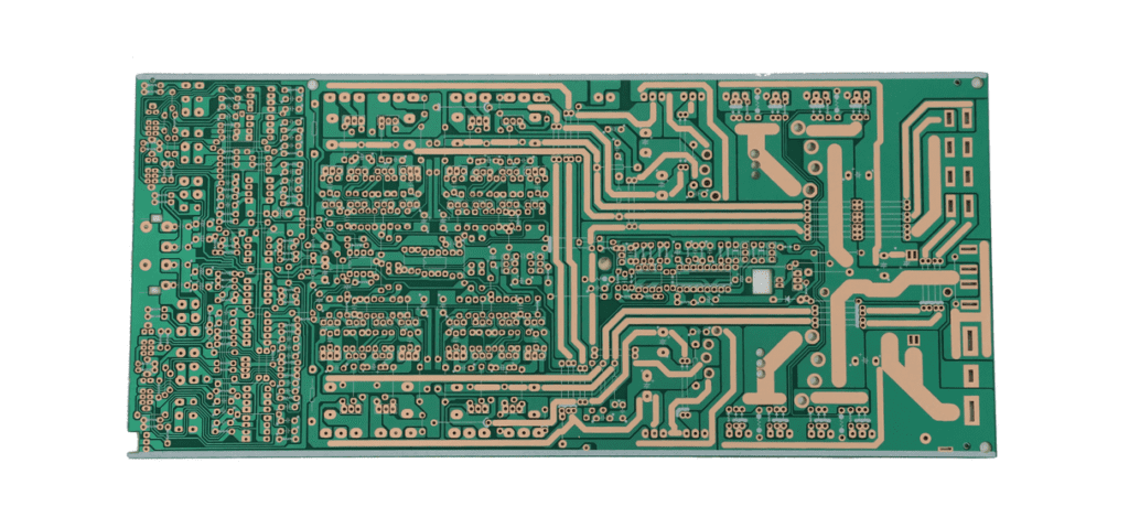
Radio Frequency and Microwave PCB manufacturing and Fabrication have grown tremendously over the last couple of years. Electronics manufacturers worldwide are heavily utilizing these two types of PCBs to get a piece of the new technology. And with the growing need for smartphones, IoT gadgets, wireless electronics, and so much more, we can only expect the demand for RF and microwave PCBs to increase. But what exactly do Radio Frequency and Microwave PCBs entail? And why should you be cautious when getting into this industry?

What exactly is a Radio Frequency Microwave Printed Circuit Board?
RF and Microwave Printed Circuit Boards function using signals that range between megahertz and gigahertz. Due to their ability to operate using such high frequencies, manufacturers utilize them to generate communication devices. Therefore, you can find these PCBs in military radars, cellphones, etc.
However, RF and microwave circuits tend to be pretty complex. Actually, due to their complexity, many engineers try to avoid them, dubbing them black magic. Therefore, you must go all in if you want to venture into RF and Microwave PCB production.
Key factors to consider when undertaking RF and Microwave PCB manufacturing
If you wish to venture into RF and Microwave PCB manufacturing, then here are a couple of tips that you should keep in mind:
Constants
When working with other PCBs, you will find that some constants, for example, dk (dielectric constants), can be utilized as single values. However, when working with RF and Microwave PCBs, things change up a little. That is because microwave and RF PCBs function under pretty high frequencies. And when different constants experience these frequencies, they automatically become more dynamic. Due to this factor, RF and Microwave PCBs become tricky to utilize.
Heat
Managing heat levels within a Printed Circuit Board is pretty vital as this helps it survive thermal stress during PCB assembly. Moreover, these thermal properties play a crucial role in layer-to-layer alignment at the drilling phase, considering that the PCB is multilayer. However, all these thermal considerations apply to most PCBs but not to RF and Microwave PCBs. That is because this two PCBs experience high heat levels when operating due to their high-frequency ranges. Therefore, when constructing or utilizing an RF or a Microwave PCB, pay extra attention to its thermal properties.
Spacing
When constructing an RF or a Microwave PCB, you should consider the spacing between components. That is because these two PCBs tend to be prone to “adjacent-feature interaction,” which might lead to short circuits.
Materials
Lastly, you should consider the materials you utilize to manufacture these two PCBs. Considerably, go for materials that can handle these PCBs’ high frequencies.
If you are a PCB designer, you should consult a PCB material manufacturer before settling on the materials to utilize. Then, after getting the suitable materials, you can pass on the design and the materials of preference to your PCB manufacturer.
The manufacturer will develop a schematic for your design and manufacture your Circuit Board to your specification.
Making a mistake at this stage might render your PCB useless or substandard. Therefore you should be careful when choosing the materials to utilize.
Some Materials that you might consider utilizing
To give an idea of some of the best materials to utilize when developing a high-frequency PCB, let us look at some components that you might use:
Ceramic Filled PTFE – these components bear exceptional mechanical and electrical stability
Heat-resistant, ultra-low loss Megtron Six – this material makes your PCB ideal for high-speed construction and HDI (high-density interconnect).
PTFE Laminate reinforced with woven glass – These laminates are lightweight and dimensionally stable, making them great for radar utilization.
Frequency difference of Microwave and RF Circuit Boards
Typically, an RF Printed Circuit Board is a Circuit board that operates using frequencies that are above 100MHz. On the other hand, a Microwave PCB is any PCB that functions using frequencies around 2GHz.
Application areas of RF and Microwave PCBs
Radio Frequency and Microwave PCBs have multiple application areas. Some of these application areas include:
– Automotive
– ATE
– Smartphones
– Computer networking systems
– Wireless technology
– Sensors
– Security and Robotics
– Telecommunication
– Military and more
Due to their impeccable frequency range, these PCBs have become pretty helpful in developing new technology. Therefore, these applications are bound to go up with time.
Tips to help you Avoid issues when working with Microwave and RF Printed Circuit Boards Designs
Microwave and RF PCBs having high-frequency laminates tend to be pretty challenging to design due to their signal sensitivity. Therefore, when developing this design, you should significantly consider the following tips:
Noise sensitivity
Microwave and RF printed Circuit Boards tend to be pretty sensitive to electrical noise. Therefore, when working on these designs, you should try to come up with a trick to help you minimize noise. Moreover, it would help if you also tried to work on lowering reflections and ringing while at the same time treating the entire system with great care.
Return Signals
RF and Microwave PCB return signals tend to take the path that bears the least inductance. Moreover, the ground planes underneath the board’s signal make this path easy to access. Therefore, you should keep this factor in mind when generating your PCB design.
Impedance Matching
It would help if you significantly considered the board’s matching impedance when developing an RF or a Microwave PCB design. That is because the boards’ tolerance goes down as the microwave and RF frequencies go up.
More often than not, your Printed Circuit Board driver will require fixing due to the high frequencies these boards experience during transmission.
Return Loss
When designing an RF PCB or a Microwave PCB, you should try your best to minimize return losses. Whether these losses are due to ringing or reflection, you should try to lower them immensely. Moreover, it would help if you kept in mind that your PCB will always find a return path. However, it would help if you tried to guide the signal flow to avoid return signal bleeding through the many PCB layers.
Characteristics Impedance
Transmission lines that curve because of routing constraints must utilize a bending radius about thrice as big as the conductor width’s center. By achieving this feat during the designing phase, you can efficiently minimize the board’s characteristic impedance.
High-Frequency Laminates
The PCB laminate material you will utilize to fabricate your RF or Microwave PCB will determine the circuit board’s durability. That is because PCB laminates provide an additional layer of protection and safety to your PCB. And considering the high RF and Microwave signals, adding on an extra layer of the shield is a pretty good idea.
PCB laminates help circuit boards easily carry out all three common variations of heat transfer. These variations are:
– Radiation
– Convection
– Conduction
You should note that thermal management tends to be of at most importance to most PCB manufacturers. And this factor becomes even more crucial when dealing with high-frequency PCBs. Therefore, when working with RF and Microwave PCBs, you should prioritize thermal management.
Tips to help you choose the right Microwave and RF Printed Circuit Board Laminate

Finding the perfect laminate for an RF or a Microwave PCB requires you to explore different properties and characteristics and then merge them to develop a solution. The process tends to be a puzzle, and without the proper guidance, you can easily fall off track and utilize the wrong laminate.
According to most PCB engineers, you should select your laminate based on how well it fits into your PCB’s application area. However, to minimize messing up your laminate choice, you should also put the following factors into consideration:
– The board’s flexibility for conformal circuits
– The board’s thickness
– Material surface profile/smoother copper
– Dielectric constant
– Thermal coefficient
– Coefficient of thermal expansion
General advantages of working with RF and Microwave Frequencies
Though complex to manufacture, RF and Microwave PCBs tend to have several advantages up their sleeve. These advantages include the following:
High Frequencies
RF and Microwave Printed Circuit Boards transfer the high-frequency signal using increased speeds and bearing less impedance. As a result, their efficiency in transferring these types of frequencies is undoubtedly unmatched.
Efficiency
Since you can develop a multilayer PCB stack-up when working with RF and Microwave PCBs. That means that you can boost the board’s performance while at the same time reducing its cost of production. Therefore, you get an efficient board at an affordable price.
Persistence
RF and Microwave PCBs offer themselves up to function in extremely high-temperature environments. However, due to their features, these PCBs tend to be pretty durable and remain persistent.
Conclusion
With RF and Microwave Printed Circuit Boards, finding the right PCB manufacturer to produce your circuit is imperative. Unfortunately, most manufacturers mess up the manufacturing procedure, while others simply avoid creating these circuits. However, though most people tend to fear these PCBs, they tend to be pretty crucial to this generation. With the emergence of smartphones, smart gadgets, wearables, IOT gadgets, and so on, you should expect to see more of these PCBs. Therefore, instead of running away from it, you should try and embrace this technology. We hope this article has shone a light on RF and Microwave PCB.


